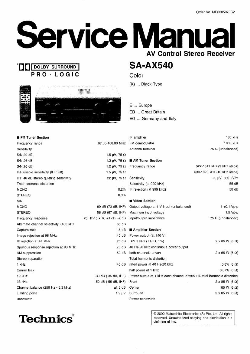
Technics SAAX 540 Service Manual

This is the 52 pages manual for Technics SAAX 540 Service Manual.
Read or download the pdf for free. If you want to contribute, please mail your pdfs to info@audioservicemanuals.com.

Page: 1 / 52
left right
Technics SAAX 540 Service Manual

Extracted text from Technics SAAX 540 Service Manual (Ocr-read)


Page 2

both channels driven, -8 dB

Damping factor
Load impedance
Front

A or B

A and B

Center

Surround

Frequency response
PHONO

CD, TAPE/MD, DVD, TV. VCR
Input sensitivity and impedance
PHONO

CD, TAPFJMD, DVD, TV, VCR
S/N at rated power (6 Q)
PHONO

CD. TAPE/MD, DVD, TV, VCR
Tone controls

BASS

TREBLE

Output voltage

10 Hz-40 kHz (6 9)
30(6 9)

4-165!
8-160
6-165!
6-169

FllAA standard pun/e (30 Hz -
15 kHz) 10.8 dB

10 Hz-40 kHz, 13 dB

3 mV/47 km
200 mV/22 kn

70dBaHF,AeOde
75dBaHF,A£5dB

50 Hz, +10 to -10 dB
20 KHZ, +10 to -10 dB

TAPE REC (OUT), VCR OUT

Channel balance (250 Hz - 6.3 kHz)
Channel separation

Headphones output level and impedance
Subwooter frequency response

I General
Power supply

Power consumption

Dimensions (W x H x D)

Mass

Power consumption in standby mode:
Notes:

200 mV

:1 dB

55 dB

430 mV/330 £2

7 - 100 Hz, :3 dB

AC 230 - 240 V, 50 Hz
(For E/EB only)

AC 250 V, 50 Hz

(For EG only)

300 W

430 x186 x 320.6 mm
92kg

2 W

1.8pecltlcations are sublect to change without notice.

Mass and dimensions are approximate

2.Total harmonic distortion is measured by the digital spectrum

analyzer.

* Manufactured under license from Dolby Laboratories. "Dolby", Pro
Logic" and the double-D symbol are trademarks of Dolby Laboratories.

A WARNING

This service information is designed for experienced repair technicians only and is not designed lor use by the general public.

It does not contain warnings or cautions to advise non-technical individuals of potential dangers in attempting to service a product.
Products powered by electricity should be serviced or repaired only by experienced professional technicians. Any attempt to service
or repair the product or products dealt with in this service intormation by anyone else could result in serious injury or death.

CONTENTS

Page

1 Before Repair and Adjustment ............................................... 3

2 Protection Circuitry
3 Accessories ~

Page

7 Type Illustrations of ICS, Transistors & Diodes .................... 12

a Terminal Functions of le-
9 Block Diagram

4 Caution for Ac Mains Lead-
5 Operation Procedures ------------------------------------------------------------ 5
6 Operation Checks and Main Component Replacement

Procedures ----------------------------------------------------------------------------- 7

10 Schematic Diagram

11 Printed Circuit Board ----------------------------------------------------------- 31
12 Wiring Connection Diagram .................................................. 33
13 Parts Location and Replacement Parts List ------------------------- 39