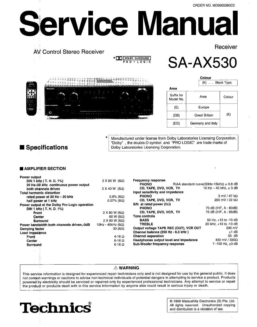
Technics SAAX 530 Schematics

This is the 56 pages manual for Technics SAAX 530 Schematics.
Read or download the pdf for free. If you want to contribute, please mail your pdfs to info@audioservicemanuals.com.

Page: 1 / 56
left right
Technics SAAX 530 Schematics

Extracted text from Technics SAAX 530 Schematics (Ocr-read)


Page 2

SA-Axsso_j

I FM TUNER SECTION
Frequency range 87.5 - 108.0 MHz
Sensitivity

SIN 30 dB 1.5 pV/7511

S/N 26 dB 1.3 uV / 750

SIN 20 dB 1.2 [JV/759
IHF uasble sensitivity (IHF 58) 1.5 V / 7552
IHF 46 dB stereo quieting sensitivity 22 pV / 750
Total harmonic distortion

MONO 0.2%

STEREO 0.3%
SIN

MONO 60 dB (73 dB, IHF)

STEREO 58 dB (67 dB, IHF)
Frequency response 20Hz - 15 kHz +1 dB, -2 dB
Alternate channel selectivity 2400 kHz 65 dB
Capture ratio 1.5 dB
Image rejection at QBMHz 40 dB
IF rejection at 98 MHz 70 dB
Spurious response rejection at 98MHz 70 413
AM suppression 50 dB
Stereo separation

1 kHz 40 dB
Carrier leak

19 kHz ~30 dB (~35 dB, IHF)

38 kHz -50 dB (~55 dB, IHF)
Channel balance (250 Hz - 6.3 kHz) 1 1.5 dB
Limiting point 1.2 pV
I Contents me
- Accessories ................................................................................... 2

- Before Repair & Adjustment/ Protection Circuitry
0 Caution For AC Mains Leads ...............................
- Front Panel Controls .
0 Basic Operations
- Dolby Pro Logic ......
0 Making A Recording
- Using the Remote Control
- Operations Checks ........

Bandwidth
IF amplifier 180 kHz
FM demodulator 1000 kHz
Antenna terminal(s) 759 (unbalanced)
I AM TUNER SECTION
Frequency range 522 - 1611 kHz ( 9 kHz steps)
530 - 1620 kHz ( 10 kHz steps)
Sensitivty 20 pV, 330 pV/m
Selectivity (at 999 kHz) 55 dB
IF rejection (at 999 kHz) 50 dB
I VIDEO SECTION
Output voltage at 1V input (unbalanced) 110.1 Vp-p
Maximum input voltage 1.5 Vp-p
Inputloutput impedance 75 Q

I GENERAL

Power consumption
Power supply
Dimensions (W x H x D)
Weight

230 W (In standby mode :2 W)
AC 230 240 V, 50 Hz

430 x 136 x 320.6 mm

8.5 kg

Notes :
1. Specifications are subject to change without notice.
Weight and dimensions are approximate.
2. Total harmonic distortion is measured by the digital spectrum
analyzer.

PAGE

0 Terminal Functions of IC's ,,,,,,,,,,,,,,,,,,,,,,,,,,,,,,,,
0 Type illustration of IC's Transistors and Diodes
0 Wiring Connection Diagram
0 Block Diagram ,
. Schematic Diagram
~ Printed Circuit Board

.17
.18
.19 ~23
24~38
39~46

. Cabinet Parts Locations . 47
¢ Repaicement Parts Us 48 ~ 50
~ Resistors 8. Capacitors 51 ~ 55

0 Packing Materials 8. Acessories

I Accessories . Packaging .................................
, 5? (ft? -
For United For Oihels @
Kingdom only
. Plug tor United
Power Supply Cord AM Loop antenna set FM indoor antenna Remote Control Batteries Kingdom ON'V

I Before Repair and Adjustment

Disconnect AC power, discharge Power Supply Capacitors C703, C704, C705 and C706 through a 109 , 5W resistor to ground.
DO NOT SHORT-CIRCUIT DIRECTLY (with a screwdriver blade, for instance), as this may destroy solid state devices.

After repairs are completed, restore power gradually using a variac, to avoid overcurrent.

Current consumption at AC 230 - 240 V, 50Hz in NO SIGNAL mode should be 240 ~ 330 mA.

I Protection Clrcuitry
The protection circuitry may have operated if either of the
following conditions are noticed :

' No sound is heard when the power is turned on.

- Sound stops during a performance.
The function of this circuitry is to prevent circuitry damage if, for
example, the positive and negative speaker connection wires
are "shorted", or if speakersystems with an impedance iessthan
the indicated rated impedance of the amplifier are used,

it this occurs, follow the procedure outlines below:
1. Turn off the power.
2. Determine the cause of the problem and correct it.
3. Turn on the power once again after one minute.

Note:
When the protection circuitw functions, the unit will not operate
unless the power is first turned off and then on again.

_2_