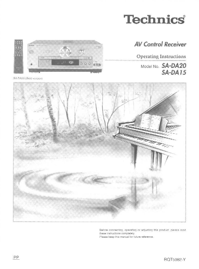
Technics SA DA20 Owners Manual

This is the 72 pages manual for Technics SA DA20 Owners Manual.
Read or download the pdf for free. If you want to contribute, please mail your pdfs to info@audioservicemanuals.com.

Page: 1 / 72
left right
Technics SA DA20 Owners Manual

Extracted text from Technics SA DA20 Owners Manual (Ocr-read)


Page 2

RQTSSBZ

Dear customer

Thank you for purchasing this product,

For optimum perlormance and safety, please read these
instructions carefully.

These operating Instructions are applicable to models
SA-DA20 and SA-DA15, however, are intended primarily tor
model SA-DAZO.

Supplied accessories

Please check and identity the supplied
accessories.

E] AC power supply cord (RJAooss-A) ............................... 1

D AM loop antenna set (RSA0012) ..................................... 1
(AM loop antenna, antenna holder, screw)

Use the numbers indicated in parentheses when asking for
replacement parts.

(Only for U.S.A.)

To order accessories contact 1-800-332-5368 or web site
(http://www.panasonic.com).

CAUTION

Do not place anything on top of this unit or block the heat
radiation vents in any way. in particular, do not place tape decks
or CD/DVD players on this unit as heat radiated from it can
damage your software

9 NO

Table of contents

Listening cautions
PRECAUTIONS,.....,,....,
Control reference guide
Connections ....................
Connecting video equipment
Connecting audio equipment
Connecting digital equipment
Antenna connections .........
Connecting the AC power supply cord and other information.
Speaker connections,
Placement of speakers
Connecting speaker

Customizing your receiver ...............
Basic steps ..................................
Adjusting speaker output level

DSP sound modes
STEREO mode...
SURROUND mod
SFC modes..,,....,,....,..

Enjoying the sound
Turning on the VGCA,
Adjusting the tone...
Adjusting the balance .
Using the VCR 3 terminals
Adjusting the subwoofer level ....................................

The radio
Manual tuning
Preset tuning

Other functions.
Muting the volume
Using the TAPE MONITOR
When using the unit in a darkene roo
Using headphones.

Making a recording.
Recording on a tape deck or

Remote control.
Batteries
Use
Button guide .
Operating the receive
Operating a DVD or CD player
Operating a TV ....................
Operating a VCR
Operating a cassette deck
To change the remote control codest

Troubleshooting guide

The HELP functio

The RESET tunctio

Maintenance .........

Product Service

Specifications.

Servicenter List (U.S.A.)

Warranty (U.S.A.)

Page 17

DSP
SOUND MODE

SFC

i:
@-
.
ES
g

DSP
SOUND MODE SFC

- PROGRAM FORMAT -

'-souNo woo: -
(SFC )

»
t
l

DSP sound modes .

Enjoy an enhanced sound experience with greater presence and.
spread by using these SFC (sound field control) modes with PCM or
analog stereo sources.

The SFC modes cannot be used if the input signal is Dolby Digital
or DTS.

. Choose from the lollowing modes.

HALL
lmparts the reflection and spread ol a large concert hall.

CLUB
Conveys the exciting and intimate atmosphere of a jazz club.

LIVE

Brings you up close tor live" stage performance and smoother
vocals.

THEATER '
Recreates natural sound ambience and direction.

- SIM SURR (Simulated Surround)

Heightens the sensation of expanded space with stereo sources.
and augments monaural sources

a Adjusting the sound field

You can adjust the sound field by adjusting the level 0! the
speakers and the delay time of the surround speakers. These
adjustments can be made tor each SFC mode.

To adjust the speaker level
G) Press [LEVEL] to select the speaker channel.
Each time you press the button:
C -- RS a LS -> SW
T_..__l
Speakers set as NONE" or NO" are skipped.
® Press [+] or [-] to adjust the level.
C, RS, and LS:
-10 dB to +10 dB
SW:
(oft) --> MIN <-» 1 - 19 «-» MAX

To adjust the delay time

0 Press [DELAY]. .

9 Press [+] or H to change the delay time.
Delay time can be set at 10-millisecond (rns) intervals between
10 and 100 ms,
The factory setting is 50 ms for each mode.

I Operations

norm

Page 28

Remote control
W I Operating (1.19m I
0 TV VCR ovo _ g _
O O O Refer to the pages In the mam operatlng instructlons tor further
details e. . .
wgojb TUNER/BAND rap): (05 ( 9 IE)
Him 0
mpuzuu uauu W To turn the unit onlofl MEWND
CD 0 m
To turn off the receiver, wnloo
cassette deck, CD player and 0
mm IIEIIIIIII DVD player
CD TV VCR DVD
0 0 To select an input source and O O 0
SK": ISEAHCN switch the remote control to TUNER/BAND up: on
(E [E E] E) each operation mode
STOP PAUSE PLAY RECEIVER
E] (I) m
5ququ CHANNEL VOLUME "1mm; To adjust the volume
new mgr)? To select the DSP sound sounn none
mode (IE) 3
m. a TVVOL + mm . To select the SFC mode src
fl (:3 [a (III) B
t] i] If] [jm To start a test signal (IE) TEST
4 5 6 mom I +
I To select the speaker channel LEVEL
I; g] I? E] and adjust its output level C_]
17 I) E]
El [:1 C] D "E "
0%)}? o alumna): nauv T0 adJ'LISt SUbWOOfer output suawoorsn
C} D level (I)
Mm mm CANCEL LEVEL +
D E] C) To change the surround E? I. [3
sum: AUDIO mm: + channel delay time (I) [i]
D C]
snow Ii? as)? - To select DVD GCH INPUT DVD SCH
[:1 [3 [:1 mode (IE) Cl
C-lwli] fl fl To select DIGITAL INPUT warm
nvp mode (IE) C]
To mute the volume (I) M%G
J L To dim the display (I) 6
To display help messages and
confirm the remote control E"
mode (I)
To select FM or AM" "8
(I) maven
To change radio channels CMNNEL
sequentially (I)
(Preset tuning)
til 6 c:
To select radio channels If] CSI 5
directly (I) 1 a n
(Preset tuning) Cl C] Cl
Col 31E?
nmscnuuma
DISC
C]
G
- To select radio stations by l 2 a
frequency (I) I? 9 C5]
(Direct tuning) [:1 Cl C)
7 l 9
Cl Cl (3
0
Cl

RQTSDBZ

Page 42

6

ROTSSSZ

g Raccordements

cable de raccordement stéréo
Blane L (G)
Rouge R (D)

cable de raccordement vidéo
-IIJ|IIIW WIIIHIII-

Pour Ie raccordemem des apparells, consulter Ie manuel

dutilisalion approprié.

Léquipemenl périphérique et les cébles sonl vendus séparémenl

saul indIcalion contraire.

0 Avant deffectuer les raccordements. s'assurer que Ie contact est
coupe sur tous les appareils.

° Utiiiser Ies raccordements numériques pour la reproduction des
signaux Dolby Digital ou DTS (-5 page 18).

0 Utiliser les raccordemenls anaiogiques lorsque ies signaux ne
peuvent pas étre decodes ou lors de I'enregistrement d'une
source (=9 pages 16, 19 et 25).

|

AUDIO OUT
(SURROUND L, R)

Lecteur DVD

S
a.
~1-J
o-l

VIDEO OUT
E

AUDIO OUT
(CENTEFI,
ESUBWOOFER IN)

rs
L4:17

AUDIO OUT
(FRONT L, H)

some 6 canaux.

Utiliser les prises d'entrée avam gauche et
% droite si la lecteur DVD ne possede pas de

Magnétoscope (lecture seulement)

omen. 1mm

mam


Prises S-VIDEO
Le raccordemeni aux prises S-VIDEO


procure une image de meilleure qualité
qu'avec Ies prises vidéo.

E .

Les signaux acheminés aux prises VIDEO
d'entrée ne peuvent étre envoyés aux
r prises S-VIDEO de sortie e! vice versa.

AUDIO OUT VIDEO OUT

VIDEO IN

VIDEO
IN

Téléviseur ou moniieur

Raccordement aux prises de magnétoscope
VCR 3 sur Ie panneau avant

VIDEO AUDIO
OUT OUT

- =
E

Magnétoscops

Caméscope. etc.