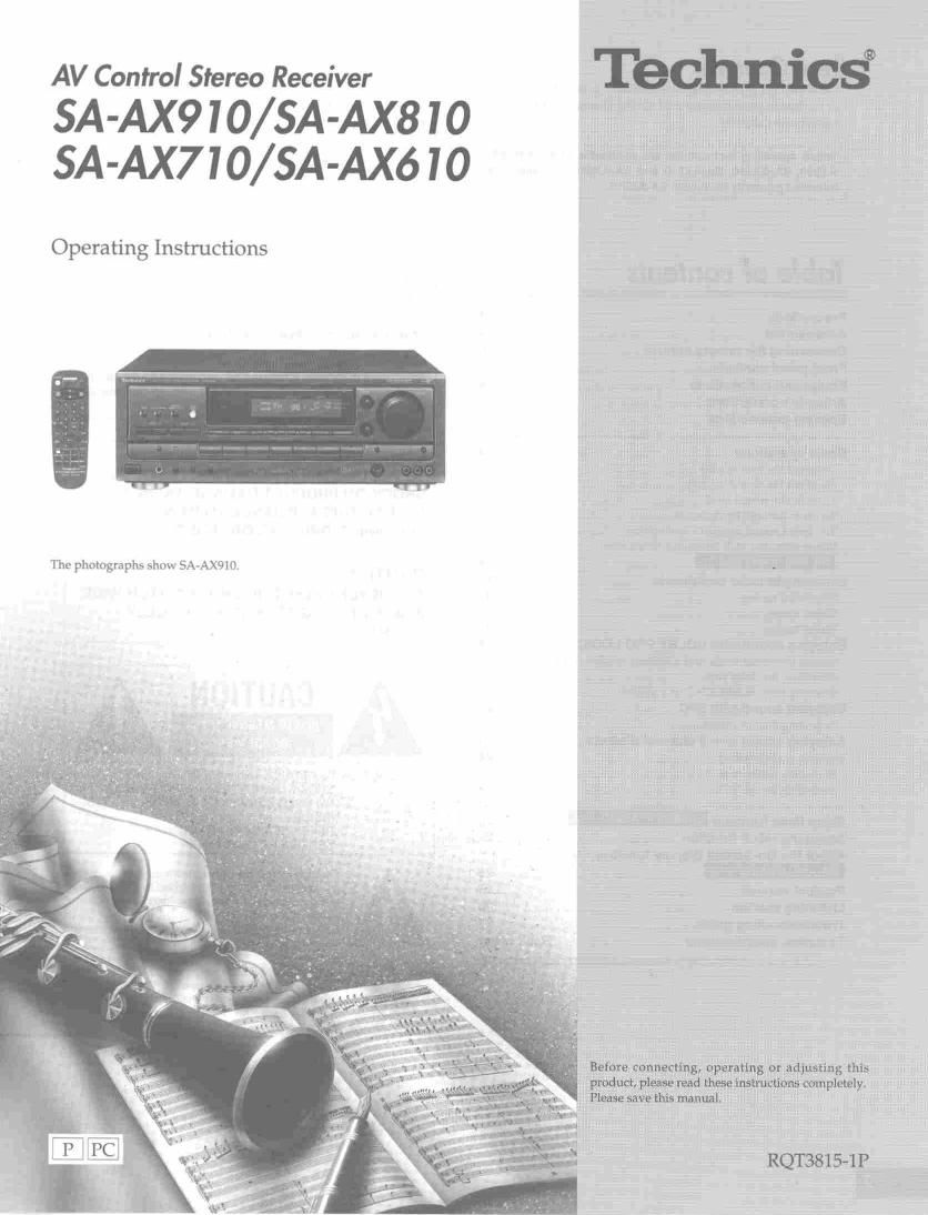
Technics SA AX 610 Owners Manual

This is the 28 pages manual for Technics SA AX 610 Owners Manual.
Read or download the pdf for free. If you want to contribute, please mail your pdfs to info@audioservicemanuals.com.

Page: 1 / 28
left right
Technics SA AX 610 Owners Manual

Extracted text from Technics SA AX 610 Owners Manual (Ocr-read)


Page 2

Dear Customer

Thank you for purchasing this Technics product.

For optimum performance and safety, please read these
instructions carefully,

These operating instructions are applicable to models SA-
AX910, SA-AXBIO, SA-AX71O and SA-AX610, however, are
intended primarily for model SA-AX910.

Table of Contents

Precautions.
Accessories
Concerning the remote control.
Front panel controls
Equipment connections
Antenna connections.
Speaker connections.

Basic operations .......
To adjust the tone quality
To adjust the sound balanc
To mute the sound level .....
To listen through headphones
To correct sound in case of low volum
When usin the VCR 2 terminal (front side)
_________

Listening to radio broadcasts
Sequential tuning.
Direct tuningr
Preset tuningr

Enjoying sound DOLBY PFIO LOGIC ................... .
Setting the center mode and adjusting speake output level .
Adjusting the delay time tttttttt
Enjoying with SURROUND or 3 STEREO

Enjoying sound with SFC.
Adjusting field of sound .....

Enjoying sound with 6 channel discret

Making a recording ,,,,,,
Recording on the tape deck
Recording on the VCR .....


User memo:

DATE OF PURCHASE
DEALER NAME
DEALER ADDRESS

TELEPHONE NUMBER

The model number and serial number of this product can be
found on either the back or the bottom of the unit.

Please note them in the space provided below and keep for
future reference.
MODEL NUMBER ..
SERIAL NUMBER

- THIS PHRASE IS APPLIED ONLY FOR u.s.A.
CAUTION:

Any unauthorized changes or modifications to this
equipment would void the user's authority to operate this
device.

WARNING:

TO REDUCE THE RISK OF FIRE, ELECTRIC
SHOCK OR PRODUCT DAMAGE, DO NOT
EXPOSE THIS APPLIANCE TO RAIN,
SPLASHINGDRIPPING OR MOISTURE.

CAUTION:

TO PREVENT ELECTRIC SHOCK MATCH WIDE
BLADE OF PLUG TO WIDE SLOT, FULLY
INSERT.

RISK OF ELECTRIC SHOCK
DO NOT OPEN

a CAUTION

Sleep timer function
About the HELP function ..............
About the On-Screen Display function

.................................................................... 26
Product service
Listening cautio
Troubleshooting guide
Technical specifications

.Back cover

CAUTIONzTO REDUCE THE RISK OF ELECTRIC
SHOCK, DO NOT REMOVE SCREWS.
NO USER-SERVICEABLE PARTS
INSIDE.
REFER SERVICING TO QUALIFIED
SERVICE PERSONNEL

The lightning flash with arrowhead symbol, within
an equilateral triangle, is intended to alert the user
to the presence of uninsulated "dangerous voltage"
within the product's enclosure that may be at
sufficient magnitude to constitute a risk of electric
shock to persons.

The exclamation point within an equilateral triangle
is intended to alert the user to the presence at
important operating and maintenance (servicing)
instructions in the literature accompanying the
appliance.

Page 8

l

Equipment comedians

Connecting a D player

Stereo conne ' n cable (not included)
White (L)

Red (R)

Before use -

(9 mm

Connecting a DVD player with 6 channel discrete output


emu

@W


[2
o suinwnnn

AUDIO OUT AUDIO OUT
(SURROUND (SUBWOOFER/
L,R) CENTER)
0 O _ - O O O
. o (-m
W

DVD player VIDEO AUDIO OUT

(not included) OUT (FRONT LR)


Video connection
cable (not included)

To adjust the input level
(CENTER LEVEL/SURROUND L LEVEL/SUR-
ROUND R LEVEL)

When connected to a DVD player or other component
with 6 channel discrete output,you can adjust input
level for the center and surround (L) and (R) channels
from these controls.

MIN \
O CENTER LEVEL
MAX 4/

Turn CENTER LEVEL to
adjust the input level of the
center Channel.

Turn SURROUND L

LEVEL to adjust the input
level of the surround (L)
channel.

MIN \

O SURROUND L LEVEL
MAX /
MIN \

O SURROUND Fl LEVEL
MAX /

Turn SURROUND R
LEVEL to adjust the input
level of the surround (R)
channel.

To connect equipment, refer to the appropriate
operation instructions.

Connecting a DVD player with 2 channel output

©©
©O

DVD player
(not included)

l o o i:] o o o
r o L-*-
"J K.)
VIDEO AUDIO
OUT OUT

r.-
\MGIEJ

Video connection

cable (not included)

Video connection
cable (not included)

You can enjoy 6 channel discrete sound by making the below connections.

DVD player (not included)

VIDEO f
OUT 0 o H :1 o o o
. o , .44.,
v v
@- DIGITAL
coma OUT
@ @ mm.
Optical A
_L digital cable
(not included)
OUT our
(SURROUN (suawoorclz/ DIGITAL
LR) CENTER) '1

LBS-l:__l_@

AC-3 decoder
(not included)

OUT
(FRONT LR)