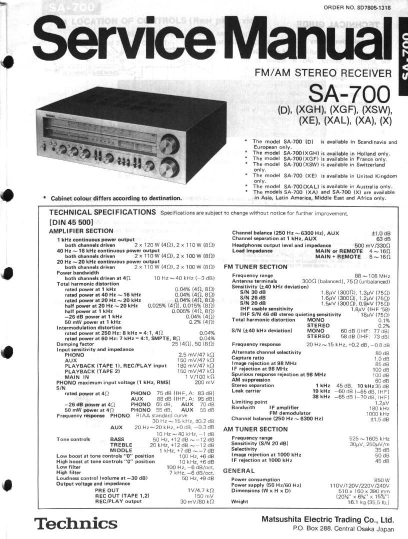
Technics SA 700 Service Manual

This is the 17 pages manual for Technics SA 700 Service Manual.
Read or download the pdf for free. If you want to contribute, please mail your pdfs to info@audioservicemanuals.com.

Page: 1 / 17
left right
Technics SA 700 Service Manual

Extracted text from Technics SA 700 Service Manual (Ocr-read)


Page 2

I TECHNICAL GUIDE

- Pow-indieltion drwltry

The power amplifier output signal is attenuated by
the sensitivity selector. and is applied to the
logarithmicoompression circuitry. In this circuitry,
as shown in figure 1, the output characteristics
change logarithmically in relation to input, and the
output is applied to the window comparator IC,
Here,
2, and the indicator illuminates according to the
input of the IC (the output of the power amplifier).

the pulse waveform becomes as shown in figure

. Tone-control circuitry

.N..[>

I ALIGNMENT INSTRUCTIONS (Main Amplifier CIrcuitry)-ENG|_|s|-| __

Lnoosv
Z 1 05
3 _- _ _____ em ______ a now an
so K
03
H >- M55
i> ,
#4 meat u
A7777777_>V(H_;GVH)___ Jr
;;,.i 7
3': l I
a» loosr
2' on

' J MIG FILY
MIDDLE Q
As =° v

BAN? PASS FILTER

Fig. 3

. Main amplifier llcol alignment ---- Refer to fig. 4.

l.

M

6.

The "Ico"adiustment should be started about 5 minutes
after setting the power switch to the ON position.

. Speakers switch to "push" position.
. Connect DC voltmeter between TP601 and Q speaker

terminal of right channel.

. Adjust VR602 to 12 mV on DC voltmeter indication.
. Connect DC voltmenter between Emitter (TR613) and

(-9 speaker terminal of left channel,
Adiust VRBOl to 12 mV on DC voltmeter indication.

. Power level indication Ilignmam ----- Refer 10 fig» 4.

1.

4s

01

Connect AC VTVM to speakers terminal. (Left and
Right channels)

. Power display switch to "ON" position and display

range switch to X0. 1" position.

. Selector Mitch to "AUX" position.
. Apply a 1 kHz signal to "AUX" terminal, (Left and

Flight channels)

. Volume control to maximum position of set.
. Adjust supply signal level to 12.6V ~ 12.7V Output of

speaker ter minal.

. Adjust VRBOl (Left channel) and VR802 (Right chan-

nel) until "200W" indicator lights up.

LIONY LP ELSE

Fig. 2

Configuration is as shown in figure a Bass and treble
are the BAX type of control circuitry, and a bandpa§
filter is used for control of intermediate frequencies.
If the middle control is moved in direction A, a
valley-like characteristic can be obtained. if it is
moved in direction B, a peak-like characteristic can be
obtained.

DC Voltmeter

(iii

MXIN REUMDTE DIEPLAV RAKGE
-r0N) 1(0N) -(xm)

Fig. 4 (Abb. 4)