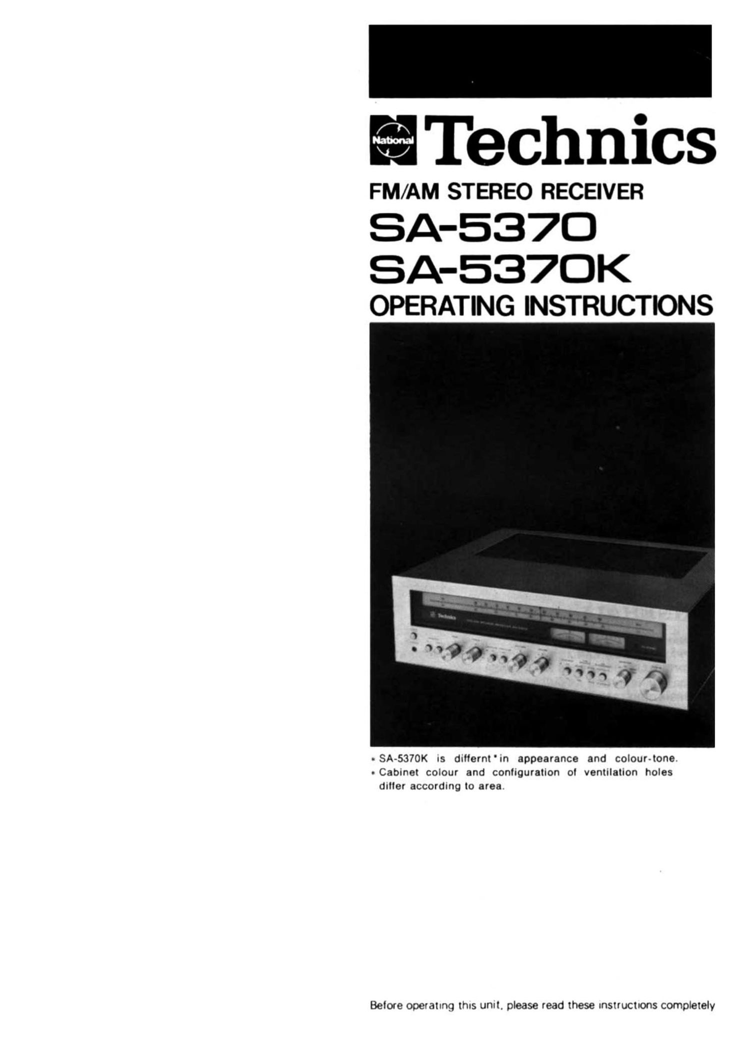
Technics SA 5370 Owners Manual

This is the 15 pages manual for Technics SA 5370 Owners Manual.
Read or download the pdf for free. If you want to contribute, please mail your pdfs to info@audioservicemanuals.com.

Page: 1 / 15
left right
Technics SA 5370 Owners Manual

Extracted text from Technics SA 5370 Owners Manual (Ocr-read)


Page 1

ITechnics

SA-537D

SA-537OK
OPERATING INSTRUCTIONS

SA-537OK IS duffernt'in appearance and colour-tone,
- Cabinet colour and configuration 0! ventilation holes
daller according to area.

Betore operatung thus unit. please read these unstructrons comptetely

Page 2

CONTENTS

BEFORE USING THIS UNIT ................................................................................................. 2
FOR UNITED KINGDOM .................................................................................................... 2
APPLIANCES CONNECTABLE TO THIS UNIT ......................................................................... 2
CONTROLS AND THEIR FUNCTIONS ..................................................................................... 3
CONNECTIONS AND OPERATION ..................................................................................... 5
OPERATION CAUTIONS ....................................................................................................... 9
HOW TO USE PIN PLUGS ................................................................................................. 10
HOW TO CARE FOR THE CABINET ..................................................................................... 10
ACCESSORIES ................................................................................................................ 10
FOR LONGER AND SAFER USE OF THIS UNIT ...................................................................... 10
TECHNICAL SPECIFICATIONS ........................................................................................... 12

Page 8

4. FM antennas have a high directional characteristic. In
other words. they are much more sensitive to PM
signals from one certain direction more than any other
direction. The antenna should. therefore. be located so
as to lace in the direction of best reception.

5. it is usually true that the higher the antenna the better.
although. depending upon the place. it may be that a
lesser height would be more advantageous. Unless
there are special conditions. therefore. a height of 12
feet (4 m) or more above the ground is suggested.

I FM broadcast reception

1. Keeping the volume control at the "0" position. press
the power pushbutton to the "ON position.

2. Set the input selector to the "FM " position.

3. Release the tape-monitor pushbuttons to theSOURCE"
position.

4. Release the FM muting/mode pushbutton to the ON/
FM AUTO" position.

5. Tune the receiver to the desired FM signal.
After roughly locating the desired FM station with the
signal-strength meter. pinpoint the position of least dis-
tortion with the FM center-tuning meter.
The stereo indicator illuminates whenever the receiver
is tuned to a stereo broadcast.

6. After pinpointing the desired station. increase the
volume to the most comfortable listening level.

7. Make other adjustments in accordance with your taste
and the acoustics ol the room.

2. Release the tape-monitor pushbuttons to the SOURCE"
position.

3. Tune the receiver to the desired AM signal.
When the best tuning has been located. the needle ol
the signal-strength meter will be farthest to the right.

4. After tuning to the desired station. increase the volume
to the most comlortable listening level.

5. Make other adjustments in accordance with your taste
and the acoustics ol the room.

RECORD PLAYER CONNECTIONS AND
OPERATION

I Connections

Connect the record player to the PHONO terminals. being
careful to connect the lelt and right connection wires cor-
rectly.

If the record player has a ground wire. connect it to the
ground ("6ND") terminal.

Lgouueérloiu megs: or AN AM ANTENNA

This unit includes a highly sensitive lerrite-bar antenna for
reception of AM broadcasts and. therefore. there should be
no necessity for connection of an outside antenna except
in an area where signals are especially weak.

I AM outdoor antenna

In weak signal areas. lar lrom broadcasting stations. or in
a relnlorced-concrete building. the highly-sensitive built-
in ferrite-bar antenna alone may lail to provide good AM
reception. if so, connect a length of vinyl-covered wire to
the AM antenna terminal (labeled "AM ANT." on the rear
panel).

Then place this antenna outdoors a short distance away
from the building. Because the sensitivity of an outdoor
antenna varies greatly with its position. someone should
listen for the strongest signals as the antenna ls oriented.
For safety reasons, the antenna should include a lightning
arrester.


Shielded cable (optional)

l.
u
Ground wire !! E
(optional) (RliLl

Record player
(optional)

"GND" terminal

"PHONO" terminals

AM outdoor antenna (optional)
AM ANT" terminal

/

Vinyl-covered wire (optional)

I Cartridge

Use a magnetic cartridge [moving-magnet type (MM). in-
duced-magnet type (IM). or high-output moving-coil type
(M0)] with an output of 2mV~10mV (50mm/sec).

If a low-output moving-coll type is used. it cannot be con-
nected directly to the phono terminals; a booster transfor-
mer or head-amplifier must be used.

I Disc performance

1. Set the input selector to the "PHONO" position.

2. Release the tape-monitor pushbuttons to the "SOURCE"
position.

3. Switch the turntable on and select the proper playing
speed.

4. Place the tone arm on the record and increase the
volume gradually to the most comlortable listening level.

5. Make other adjustments in accordance with your taste
and the acoustics ol the room.

CONNECTIONS TO THE AUXILIARY INPUT

TERMINALS AND OPERATION

I AM broadcast reception
1. Set the input selector to the AM" position.

These terminals are for connection with the output terminals
oi a tape deck or 8-track stereo. a semiconductor cartridge
with head amplifier. etc.

I Reproduction

1. Set the input selector to the AUX" position.

2. Release the tape-monitor pushbuttons to the SOURCE"
position.

3. Sound will be heard by operating the sound source and
turning the volume control clockwise.