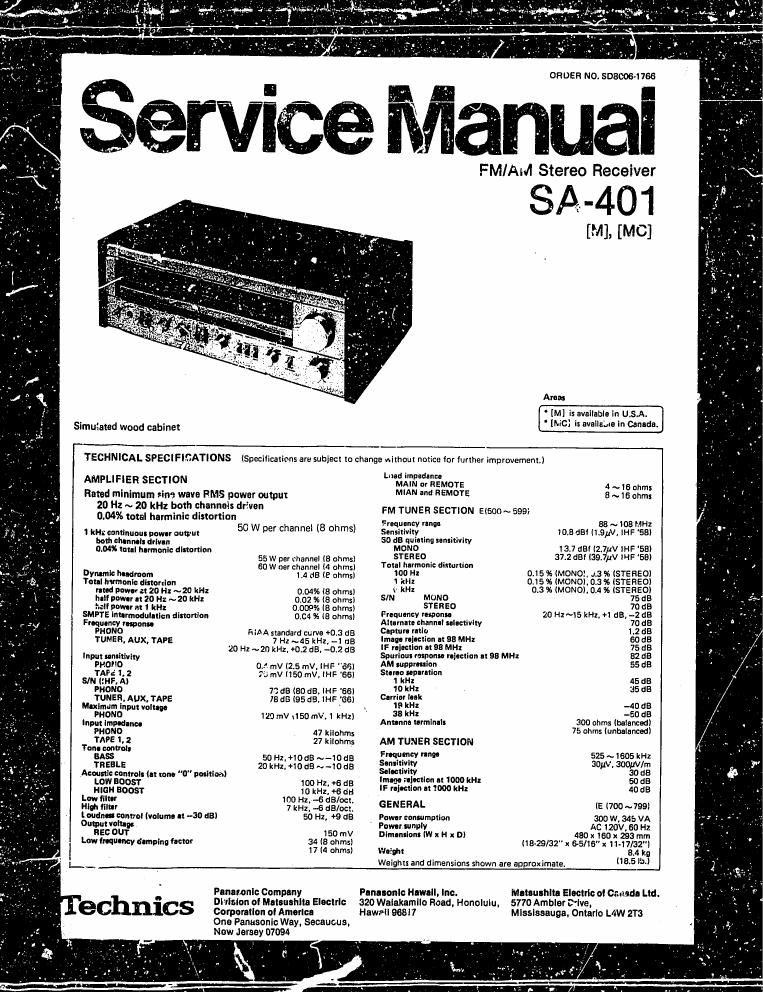
Technics SA 401 Service Manual

This is the 9 pages manual for Technics SA 401 Service Manual.
Read or download the pdf for free. If you want to contribute, please mail your pdfs to info@audioservicemanuals.com.

Page: 1 / 9
left right
Technics SA 401 Service Manual

Extracted text from Technics SA 401 Service Manual (Ocr-read)


Page 2

I coil-rears

LOGRTIDN OF CCMYROLS . . . . . . .
DISWEMBLY INSTRUCTION
VARIABLE RESISTOR? = .....
ALIGNMENT INSTRUCTIQNS
ALIGNMENT Palm. . .
BLOQKDIAGBAM... .....l
' DIAL CORD INSTALLATION GUIDE
BLOCK DIAISRAMOF IG'S . .
PRINTED KNIT BOARD WI ,
IFMIAM wwwmdlurdrwhbml . . . . . . . . .12,13
FRINIEfi CIRCUIY BOAIID WIRING VIEW
, (Toni. min «whim, pointer-poly no Wot

rEnmnAL euro: or: numerous e "rs . . . . . . . .13. g .
by a. (gmfdm ,
use an ac wpl ........
REILAGEMFINT unveils? (E'malc pm). . .
wuemrrcmmnm
REPLACEMENT mars LIST
(Humor: a. «mum. . . . . .

.prrmmelrwltbml..........f.........14.151,"

i LOCATION OF con-rams

Power level indicators

Le! Rix

Program indicators
Signal strength indicators

rFiVl stereo indicator
L

J ,

l-leadlzhones--l
Speakers
(remoteamaino-vmain and remote)
Power display range selector
(X0.1-- X1~offl B

ass--
Treble-
lBoosr-v-offo-ofilter) Low..-

(Roostvr off-r filter) High

FM muting/mode
(en/FM autm-off/FMmonol

(sourceM tape 2)

Te e monitor
~-(sourcevtape 1)} p

Loudness (off-om

r-Balance

Rec out

Tape I

Playback

rMain speakers

L LSelector(AMHFM--nhanov-aux)

LED indicator
urlve circuit

AM RF. FM IF
DET. 81 MPX [(2

FM RF amplifier
Variable capeclror
AM bar antmr:

Equalizer amplifier
. 'cu it

I DiSASSEMBLY INSTRUCTIONS

How to remove the top board

1, Remove the 3 setscrews (Fig. 1 : ®~@) hold»
in; the top board and ventilation.

2 Move the top board and ventilation slightly
toward the rear of the unit (Fat 1 : 0 L

Ventllotlen

V.
(D

' How to remove the front panel and the bottom board
1. Loosen the 4 setscrews (Fig. 2 : 8}» (D) holding the side boards.

Top board

(Fig. ll

2. fiemove the 5 setscrews (Fig. 2 :' ~ ® ) holding the front panel and remove the 2 setscrews (Fig. 3 : 03) , ® ) holdlng

the bottom board.
3, Pull the front panel outward from the front of the unit,

4. To remove the bottom hoard. remove the 12 serscrews (Fig. 3 : 33 ~ Q}? l holding the bottom board.