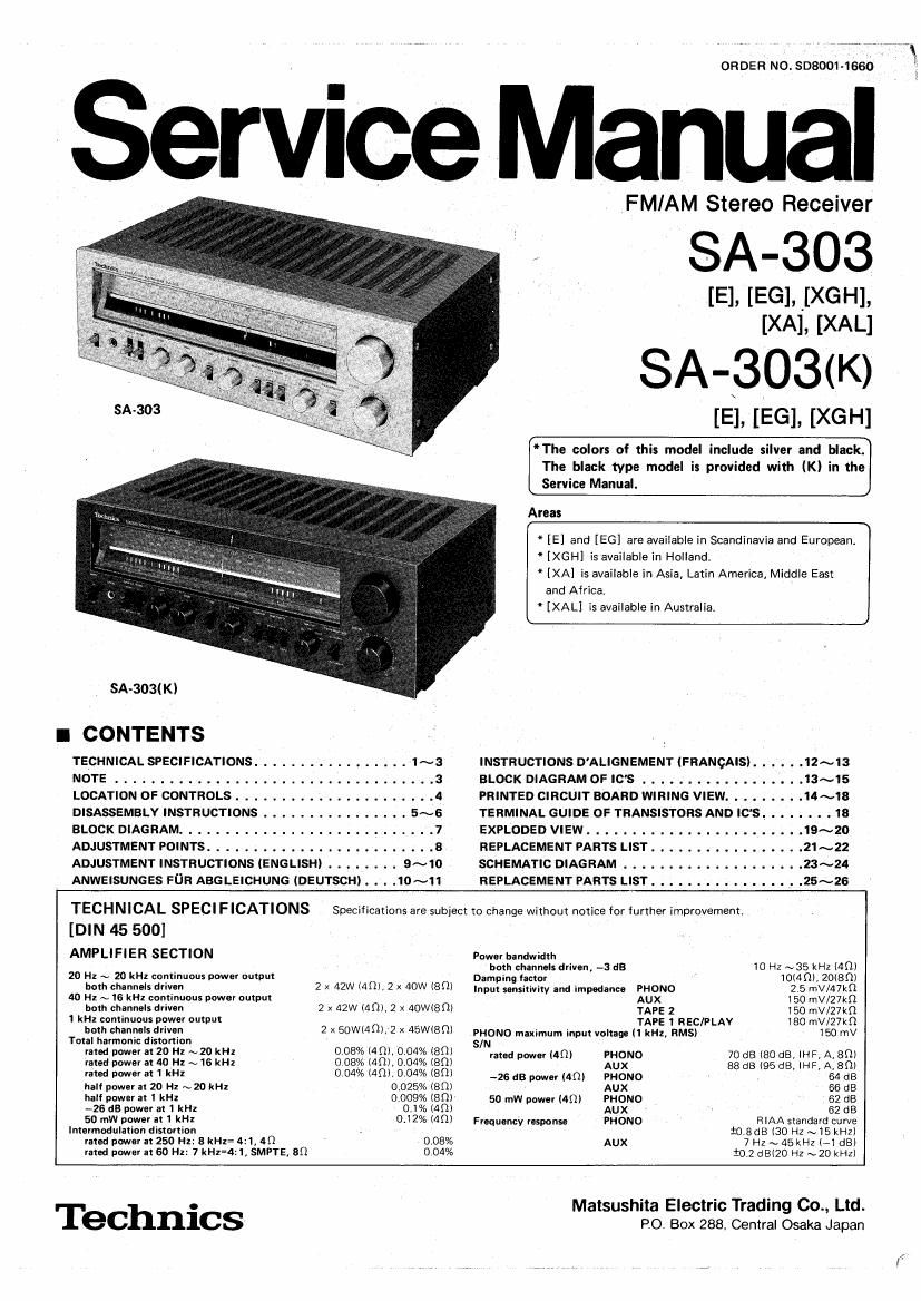
Technics SA 303 Service Manual

This is the 21 pages manual for Technics SA 303 Service Manual.
Read or download the pdf for free. If you want to contribute, please mail your pdfs to info@audioservicemanuals.com.

Page: 1 / 21
left right
Technics SA 303 Service Manual

Extracted text from Technics SA 303 Service Manual (Ocr-read)


Page 1

ORDER No. 308001-1660

Service Manual

FMIAM Stereo Receiver

, SA-303

[E]. [EG]. _[XGH],
[XAL [XAL]

SA-303(K)

[E]. [EG], [XGH]

*The colors of this model include silver and black.
The black type model is provided with (K) in the
Sarvice Manual.

Areas

* [E] and [EG] are available in Scandinavia and European

[XGH] is available in Holland,

* [XA] is available in Asia, Latin America, Middle East
and Africa.

* [XAL] is available in Australia.

SA-303IK)

l CONTENTS

TECHNICAL SPECIFICATIONS ................. 1~3 INSTRUCTIONS D'ALIGNEMENT IFRANGAISI. . . . . .12~13
NOTE..... .....3 BLOCKDIAGRAMOFIC'S..................13~15
LOCATION OF CONTROLS . PRINTED CIRCUIT BOARD WIRING VIEW. 14~1S

DISASSEMBLY INSTRUCTIONS . . . . TERMINAL GUIDE OF TRANSISTORS AND ICS. . . . . . 18
BLOCK DIAGRAM ............. . . . EXPLODED VIEW . . ........ . . 19~20
ADJUSTMENT POINTS ................ REPLACEMENT PARTS LIST . . . . . 21~22
ADJUSTMENT INSTRUCTIONS (ENGLISH) . . , SCHEMATIC DIAGRAM . . . . . . . . 23~24
ANWEISUNGES FUR ABGLEICHUNG (DEUTSCH) . .10~1I REPLACEMENT PARTS LIST ................. 25~26
TECHNICAL SPECIFICATIONS Specifications are subject to change without notice for further improvement.
[DIN 45 500]
AMPLIFIER SECTION Powerhandwidlh
both channels driven, -3 dB 10 Hz ~35 kHz 14m
20 Hz ~ 20 kHI continuous power output Damping [actor ' 1014(1). 20mm
both channels driver- 2 x 42W 44m, 2 x 40W 80) Input Mammy and impedance mono 2.5 mvmm
40 Hz ~ I6 kHz continuous power output AUX 150 mV/27kQ
both channels driven 2 x 42W 14012 x 40Wl8 m TAPE 2 150 mV/27kn
1 kHz cominuous power output TAPE 1 REC/PLAY 180 mV/27kfl
both channelsdrivln 2 x 50w14m,2 x 45W18m pHoNo "mama. input voltage (1 kHz, RMS) 150 mV
Total harmonic distortion 0 08% 14m 0 04% (80) S/N
mad power as 20 Hz ~20 kHz . , n p 70 dB (80 dB, IHF, ABC)
rated power at no Hz ~16 kHz 0080/n 1401,0049u (an) mm pm I I IBM 88 dB 195 dB, ma, A, an)
rated power at 1 kHz 0.04% (Am, 004% (an) _26 as um", um pHONo , p 64 dB
hall power It 20 Hz ~20 kHl 0.025% (an) AUX 66 dB
half power at I kHz 0.009% (80) 50 mw power (4!!) PHONO 62 dB
-26 113 power at 1 kHz 0.1% (40) AUX - 82 dB
50 mW power a! 1 RH! 012% (40) Frequency response PHONO RIAA standard curve
Intermodulation dismnion . to ads (30 H1 ~15 kHz)
mod powomzso Hz:5kHz= 6:1,40 0.08% Aux 7Hz~45kHZ (E1 dB)
rated power at 60 H1: 7 kH1=4:l, SMPTE, Sn 0 04% $0.2 dB(20 H2 ~20 kHz)

Matsushita Electric Trading Co., Ltd.

TeChnics Po. Box 288, Ceniral Osaka Japan

Page 20

1 2 I 1 3 I 14 I 1 5 . 1 6 I 1 7 I 18 I 1
I POWER SOl
osgxsoz 0603 SUP I753! 3 OTHER PR(
2 l l2?) 2 SC | 8 l5
ens DRIVE RIFF'LE'FILTER . Pmduct for
- AK wszs
0603 I/4 IO 40 2 . . l 1
WW AN 7060 ' Posmve volta e '
DIFFERENTIAL AMP 53 1: ,
a: :, csss (40.2V) Me
,I SZOKI '. so: 2 3 5 6 ml 7 a s 2253 u 3 H zoozz
. I .
32 Hell I": 33
_IT I ' Lax 35 :33 I
13 XI .. W 3*
ntroI :I 3: C2537 2: - I, z? (a: 9 [MRI I
L J ns03 Recs 33 3° I »- V '5
47x sex I '9 _o 7 I
HA "P :5 g: I: 603 3 LGOI Fsoi 2.5A .
° &68°29K s" I A
m -N r) n
g I H a o g In 2 06H x - 2 3 II
4 g in n 22? o 2: cszs
IE 9;} §+ g "I: <1 '3 + 0.047 _
t 0 z F0>
_x Q 39 R627 : fifi s (9 Lch OP
Bu} _ u> D DI _ ro
trol/ I 3 i It ' "5 f} a 4,162.30 MA I062FV O Ea;
3 «0 MA | N
'39 ._
o) ,
B It; 503,504 I; I4 - 4 Rch
w m AN 7060F SVISTK I039 | {-9
DIFFERENTIAL AMP PM" mp |
2% III I I I
u I 2 4 6 In I
5 I
use: csoa K
I Q Aeszz I ll 6)
I" l 2
control 3| I § I c-°*°- / a 9 LC
Iol l I; | / o-
"I I (I | / ss- 4 R E MOTE
L- J v A : IL J 0
I20 A E ******* R ch
nsoe Halo 7 7° ®
a: E_ SVDS4VB|O MAISO
o.- ,
EN 0 u + N I
Q: E: D 702 I 703 IngN-I;
I I MA 2 IBOB 2
. _ . '" , r " V" " , Anzsovm
i tsv 33% EA 300 3
I'M- a A F2
. -> - No _ o X zsovtsn
0,. o is In 0 N a I
I r~ r- v o c -r
§- It; .2 z 2;; IfII-I I, 9.0L, M
:x ., - g?- BLUI
2 Bass control ' N L o o N! war
3 g 5 x 8 A 9 73 3 SI ELK AC Io
- g g I6: I xo.l I: g g 3 ya; A
n 0 N N CIOOI 0.0I
3 3 ° -°le El E3! xxn 34; E n: REDI El
x I: s7-2 1-; PF I, + 3 E g + S ' .
aim I" o v u NegatIve voltage (-40.2V) Me I ,.
:31 I IBLU I A "I
we, ,_ I: I I I
°°L M - 2535301 I I Ass-2
20 I? Is I9 I IL 7777 I L
20 I? Is Is $0002 cm
3 3 Kahlé552l: 0603.804
3 3 on: I. cum zsc 828
3g gm if new: AMP
so: cool '0
I X 0 ° 0 0602
_ . ., z 7 ' +L-osoa
I .. s
r - V-1 - Icaos 0];
I 0| I In a;
I 5. I I a I El I n E LE
I "3 El IPOWER | gas
I O | llfNESIEk-ron | . El 5 II 3 Notes:
| I | M I g a 3:; o 34;, PL 2 1. S1-1~S1-6: Selector switch in "FM" position. (D AM <4 ® PM --> @pr
ol I I 32 g "3 3" 3 2. 82-1 ~ 82-3: FM muting/mode switch in "on/FM auto" position.
In El I I K I 3. 83-1 ~83-3: Tape monitor I switch in "source" position. Source H tape 1
2 5' I I it 4. 84-1 ~S4-3: Tape monitor 2 switch in source" position. source tape 2
\\ :I | - DeoI~ nos P 5. 85-1, 5-2: Loudness switch in off" position.
|l I \\ MA I 5 O 5 6. 86-1, 6-2: High filter switch in "off" position.
I | I 7. 87-1, 7-2: Power display range switch in "X1" position ®X0_1H®X1-v
I00 I:
I I PL 8. 88-1, 8-2: Speakers selector switch in "main" position ® remote +- ®
I I \\ g A N 6875 9 89' Power source switch in "on" position
I . . .
I I 0 GD 9 I: I LED COMPARATOR 10. S10: Voltage adjuster switch in "240V" position. 120V « 110V -
I I \\' h _ PL5 11. Indicated voltage values are the standard values for the unit measured by
| I '2 69 § I with the chassis taken as standard, Therefore, there may exist some erron
l I \\ impedance of the DC circuit tester.
| I 44 69 g PLs I:| Not apply signal to set and muting switch to OFF condition,
I | ' a I I AM signal reception.
I | \\_ g I '- _I FM muting to ON condition.
I | "6 98 my ( ) FM stereo signal reception,
I I Q - 7 12_ :2»??? AI: signal lines. I=(> FM signal lines. AM signal lines.
I I Eco: } ' 7 13. A indicates that only parts specified by the manufacuturer be used for safet
|
| I gall: PLB
. I | . .
'g I I = I ShortIng SWItch
' | I I.s GD °° I . . . . . . . .
3 I I I' 3 PL9 ThIs unIt uses a shortmg SWItoh. As Illustrated below, the CITCUH Is sht
E I I 44 GD I30 I Ic :02 A N 6875 In the circuit diagram, the shaded area represents the common terminz
D I | ' I. a LED COMPARATOR
KI I I 2 ___-WE] PLIO
Egl I '2 [GD 2 I I 2 3 4 5 s 7 a 9 Connected to circuit A Circuit A is shorted to circuit B Connected to circuit
I I Ran " "'
oz |
:5: I 40 GD IE I -o .9
u
«I I I' __
_zI I m
:9 I00 1D is | SU p
«II I
D I I I O SUP I753|A |75IIB Common A B Common A B Common A B
|
__ _ _ J ___ _ J