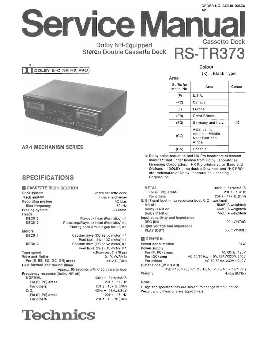
Technics RSTR 373 Service Manual

This is the 46 pages manual for Technics RSTR 373 Service Manual.
Read or download the pdf for free. If you want to contribute, please mail your pdfs to info@audioservicemanuals.com.

Page: 1 / 46
left right
Technics RSTR 373 Service Manual

Extracted text from Technics RSTR 373 Service Manual (Ocr-read)


Page 1

ORDER NO. A0940100660

ervice Manual

Dolby NR-Equipped

Cassette Deck

Stereo Double Cassette Deck RS_T R373

*
u_

AR-1 MECHANISM SERIES

SPECIFICATIONS
I CASSETTE DECK SECTION
Deck system Stereo cassette deck
Track system 4-track. 2-channel
Recording system AC bias
Blae irequency 80kHz
Erasing system AC erase
Heads
DECK 1 Playback head (Permalloy)><1
DECK 2 Recording/Playback head (Permalloy)x1
Erasing head (Double-gap ferrite)>< 1
Motors
DECK 1 Capstan drive (DC servo motor)x 1
Reel table drive (DC motor)>< 1
DECK 2 Capstan drive (DC servo motor)x 1
Reel table drive (DC motor)x 1
Tape speed 4.80mlsec. (1-7/8ips)

Wow and ilutter
For (E, EB, E6, 60. GN) areas
Fast iorwerd and rewind times
Approx. 95 seconds with 0-60 cassette tape
Frequency response (Dolby NR oii)

0.1% (WRMS)
:0.2% (DIN)

NORMAL 40Hz-15kHzt3dB
For (P, PC) areas 20Hz-17kHz
For others 20H1716kHz (DIN)

Cro, 40HZ-15kHziSdB
For (P, PC) areas 20Hz-17kHz
For others 20Hz-16kHz (DIN)

Technics

Colour
(K) Black Type
Area
3:2: Lo; Area Colour
(P) U.S.A.
(PC) Canada.
(E) Europe.
(EB) Great Britain.
(EG) Germany and Italy. (K)
Asia, Latin,
23:23:32?
Africa.
(GN) Oceania.

* Dolby noise reduction and HX Pro headroom extension
manufactured under license from Dolby Laboratories
Licensing Corporation. HX Pro originated by Bang and
Olufsen, DOLBY, the double-D symbol and HX F'FlO
are trademarks of Dolby Laboratories Licensing
Corporation.

METAL 40Hz-16kH213dB
For (P, PC) areas 20Hz-18kHz
For others 20Hz-t7kHz (DIN)

SIN (Signal Ievel=max recording level, CrO, type tape)
NR 0" 56dB (A weighted)
Dolby 8 NR on 66dB (A weighted)

Dolby C NR on 74dEl (A weighted)
input sensitivity and impedance

REC (IN) 100 mV/47 k0
Output voltage and impedance

PLAY (OUT) 500mV/5000
I GENERAL
Power consumption 24W

Power supply
For (P, PC) areas
For (60) area
For others
Dimensions (w x H x D)
430 X 136 X 285mm (1645/16" X 56/16" xii-7132")
Welght 4.4 kg (9.7 lb.)

AC 60HZ, 120V
AC 50/60HZ, 110V/127V/220V/240V
AC SOIGOHZ, 230V-240V

Note:

Disign and specifications are subject to change without notice.
Weight and dimensions are approximate.

Page 2

RS-TR373

ICONTENTS

SAFETY PRECAUTION
CONNECTIONS .
CAUTION FOR AC. MAINS LEAD
FRONT PANEL CONTROLS
PLAVBACK..
RECORDING
ACCESSORIE
TO MAKE A SILENT INTERVAL
TO ERASE RECORDED SOUND
SELF-DIAGNOSTIC ..
DISASSEMBLV INSTRUCTION
WRITING TO EEPROM ..............
MEASUREMENTS AND ADJUSTMENTS


WIRING CONNECTION DIAGRAM
TROUBLESHOOTING GUIDE
TERMINAL FUNCTION OF [0.
PRINTED OIRICUIIF BOARDS
SCHEMAIIC DIAGRAM
BLOCK: DIAGRAM
TERMINAL GUIDE
PACKAGING

CABINET PARTS LOCATION
REPLACEMENT PARTS LIST .
MECHANISMI PARTS LOCATIO
REPLACEMENT PARTS LIST.
RESISTORS AND CAPACITORS

I SAFETY PRECAUTION (This safety precaution is applied only in USA.)

f-"PPPH

Before servicing, unplug the power cord to prevent an electric shock.

When replacing parts, use only manufacturer's recommended components for safety.

Check the condition of the power cord. Replace if wear or damage is evident.

After servicing, be sure to restore the lead dress, insulation barriers, insulation papers, shields, etc.

Before returning the serviced equipment to the customer, be sure to make the following insulation resistance

test to prevent the customer from being exposed to a shock hazard.

O INSULATION RESISTANCE TEST

1. Unplug the power cord and short the two prongs of the plug with a jumper wire.

2. Turn on the power switch.

3. Measure the resistance value with ohmmeter between the jumpered AC plug and each exposed metal cabinet
part, such as screwheads antenna, control shafts, handle brackets, etc. Equipment with antenna terminals
should read between 3M0 and 5.2MQ to all exposed parts (Fig. A). Equipment without antenna terminals
should read approximately infinity to all exposed parts (Fig. B).

Note: Some exposed parts may be isolated from the chassis by design. These will read infinity.

Antenna
terminal

Exposed
metal
part

Ohmmeier

(Fig. A)
Hesistance:3 MO-5.2 M0

Exposed
metal
part

E; ; Ohmrneter

(Fig. 8)
Resistance:Approx, (I)

4. If the measurement is outside the specified limits, there is a possibility of a shock hazard. The equipment
should be repaired and rechecked before it is returned to the customer.

Page 7

Reverse function

The reverse function on this unit has three modes (2 . (I),
00). Read the descriptions below and select the mode as
desired.

Mode Tape travel

Only one side of the tape (either the torward side
-+ or the reverse side) will be played. and operation
4- will automatically stop when playback has been

completed.

Both sides of the tape will be played repeatedly
eight times, and then operation will automatically
stop.

(It playback is begun from the reverse side, the tor-
ward side will be played seven times.)

When there Is a tape In only one of the decks
Both sides of the tape will be played once, and
then operation will automatically stop.

(it playback is begun irom the reverse side, the for-
ward side will not be played.)

When there is a tape In each ol the decks
The torward and reverse sides of the tape in Deck
1 will be played. followed by the iorward and
reverse sides at the tape in Deck 2, and alter this
operation is repeated eight times, operation will
automatically stop.

(if playback is begun from Deck 2, the tape in
Deck 1 will be played seven times.)

(I)

About the automatic-tape-select
function

This unit is equipped with the automaticrtape-select feature, it
automatically detects the type oi tape being used, and then
makes the suitable adjustments or the bias and equalization ac-
cordingly.

About the remote control function

when connecting a Technics amplifier with the remote control
transmitter to this unit. you can operate this unit using a remote
control transmitter of the amplilier,

(See the operating instructions of the amplifier)

During operation irom the remote control, the RC." indicator

Deck 2 "RC.
indication

Deck 1 RC."
Indication

R R373

About the Dolby noise-reduction
system

The Dolby noise-reduction system is designed to effectively redu»
co the annoying high-frequency "hissing" noise typical oi
cassette tapes. During recording, the system lunctions to in-
crease the high-lrequency sound level, the sound, and then, dur-
ing playback. that same portion is weakened to bring it back to
the previous level.

This unit includes two types of Dolby noise-reduction systems.
the Dolby B NFt-type and C NR-type.

Dolby B-type noise-reduction

Noise is reduced to about one-third.

Use this system when playing back tapes recorded by the Dolby~
B noise-reduction system, such as prerecorded music tapes, etc.

Dolby C-type noise-reduction

Noise is reduced to about one-tenth.

Use this system tor the recording and playback of sound sources
that have a wide dynamic range and good tone quality. such as
FM broadcasts of live perlorrnances, etc, and for playing back
such tapes.

About the Dolby HX-Pro headroom
extension system

By lunctioning to improve the maximum output level oi the tapes
high-frequency range, this system permits recordings without a
reduction in the level or the sound sources highlrequency
range. In addition, by using the system in parallel with this unit's
noise-reduction system. recording and playback with a greatly ex
tended dynamic range is possible.

Dolby noise reduction and HX Pro headroom extension
manufactured under license from Dolby Laboratories Licens»
ing Corporation. HX Pro originated by Bang & Oluisen.

DOLBY, the double-D symbol DC] and HX PRO" are
trademarks of Dolby Laboratories Licensing Corporation.