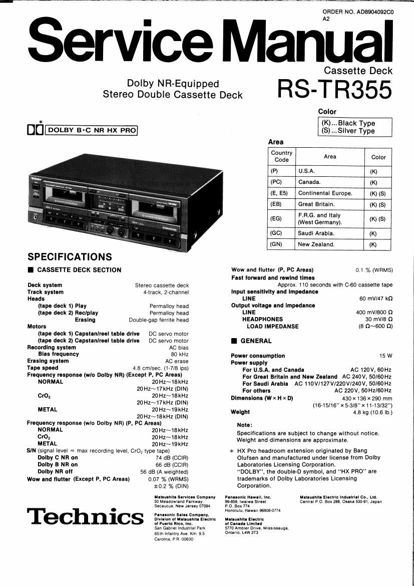
Technics RSTR 355 Service Manual

This is the 39 pages manual for Technics RSTR 355 Service Manual.
Read or download the pdf for free. If you want to contribute, please mail your pdfs to info@audioservicemanuals.com.

Page: 1 / 39
left right
Technics RSTR 355 Service Manual

Extracted text from Technics RSTR 355 Service Manual (Ocr-read)


Page 1

ORDER NO. A0890409200

Service Manual

. Cassette Deck
SteregngnSg-gggsggtdeeck R S'T R35 5

Color

* (K)... Black Type
DE] DOLBY B-c NR HX PRO (8) ...Si|ver Type
Area
Country
Code Area Color
(P) U.S.A. (K)
(PC) Canada. (K)
(E, E5) Continental Europe. (K) (5)
(EB) Great Britain. (K) (S)
F.R.G. and Italy
(EG) (West Germany). (K) (8)
(GO) Saudi Arabia. (K)
(GN) New Zealand. (K)
I CASSETTE DECK SECTION Wow and tlutter (P, PC Areas) 01 % (WRMS)
Fast lorwerd and rewind tlmes
Dock system Stereo cassette deck Approx. 110 seconds with C-SO cassette tape
Track system A-track, 2-channel Input sensitivity and Impedance
Heads LINE 60 mVl47 k0
(tape deck 1) Play Permalloy head Output voltage and Impedance
(tape deck 2) Rec/play Permalloy head LINE 400 mV/BOU 0
Erasing Doublegap ferrite head HEADPHONES 30 mV/B Q
Motors LOAD IMPEDANSE (B O~600 Q)
(tape deck 1) Capstanlreel table drive DC servo motor
(tape deck 2) Capstanlreel table drive DC servo motor I GENERAL
Recording system AC blaS
Bias Irequency 80 kHz Power consumption 15 W
Eresmg system AC erase Power supply
I 599° 4 8 cmlsecv (1-7/8 78) For U.S.A. and Canada AC 120v, 60Hz
Frequency response (wlo Dolby NR) (Except P. PC Areas) For Great Britain and New Zealand AC 240V, 50/60 Hz
"WW- ZOHZNIBKHZ For Saudi Arabia AC 11ovr127vr220w240v, 50/60Hz
20HZ~17KHZ (0W) For others AC 220v, 50Hzl60Hz
Cro, 2° HZ~18KHZ Dlmenslons (w x H x D) 430 x 136 x 290 mm
20 HZNVkHZ (D'N) (16-15/16 x 5-3/8x11-13/32")
MET- 2°H1N19KHZ Weight 4.8 kg (10.6 lb.)
20 H2~18kHz (DIN)
Frequency response (wlo Dolby NR) (P, PC Areas) Note:
grooRMAL :g::~1§::: Speclfloations are subject to change without notice.
2 ~ W .
METAL 20Hz~19kHz elght and dlmensrons are approximate.
SIN (signal level : max recording level, CrO; type tape) >l< HX Pro headroom extension originated by Bang
Dolby 0 NR on 74 dB (CCIR) Olufsen and manufactured under license from Dolby
Dolby B NR on 66 dB (CCIR) Laboratories Licensing Corporation.
Dolby NR 0" 56 dB (A weighted) DOLBY, the double-D symbol, and HX PRO are
Wow and Ilutter (Except P, PC Areas) 0.07 % (WRMS) trademarks of Dolby Laboratories Licensing
10.2 % (DIN) Corporation,
Mluulhlll Servlcu Comp-fly Plnleonlc lelll, Inc. Menu-nit. Elootrlc lndullllll 00., let
50 Meadowland Parkwey 99-859. lwalwa Streel Central P O. Box 288. Onke 530-51. Japan
Secaucus. New Jersey 07094 PO. Box 774

Honolulu. Hawlll 9680870774

.
PInleonlc Snln Company,
1 mmlon oi M-uulhltl Electric mumm- Electric
ol Puorlo Rico. Inc. at Canada lenou
San Gabriel lnouslllal Park 5770 Ambler Drlve Mlssrsseuge.

65th lnlantry Ave Km 9 5 Ontario Law 2T3
Carolina. P R 00630

Page 2

m-

I CONTENTS

Page

OSalety Precaution 0 Block Diagram... 30, 31


OAccessories ......... OWiring Connection Diagram 32
-How to Connection OResistors 8t Capacitors ........ 3~36
0 Location of Controls ....... 'Replacement Parts List (Electrical Parts 37~39
- Disassembly Instructions .. ICabinet Parts Location .......................... 40, 41
OMeasurement and Adjustment Methodes. . 10~12 OReplacement Parts List (Cabinet Parts). . 42
-Terminal Function of lC's .. . 13~15 Replacement Parts List
Ointernal Connection of FL. ..... 16 (Mechanical Parts) (DECK 1) ........................... 43
IPrinted Circuit Boards . 17~21 tMechanicai Parts Location (DECK 1) .............. 44, 45
oSchematlc Diagram... . 22~29 'Replacement Parts List
~Termina| Guide of ICs, (Mechanical Parts) (DECK 2) ............. 46
Transistor and Diodes ..................................... 29 OMechanical Parts Location (DECK 2) ....... . 47, 48

I SAFETY PRECAUTION (This safety precaution" Is applied only in USA.)

. Before servicing, unplug the power cord to prevent an electric shock.

. When replacing parts, use only manufacturer's recommended components for safety.

. Check the condition of the power cord. Replace if wear or damage is evident.

. After servicing, be sure to restore the lead dress, insulation barriers, insulation papers, shields, etc.

. Before returning the serviced equipment to the customer, be sure to make the following insulation resistance test to
prevent the customer from being exposed to a shock hazard.

UlAmN

. INSULATION RESISTANCE TEST

1. Unplug the power cord and short the two prongs of the plug with a jumper wire.

2. Turn on the power switch.

3. Measure the resistance value with ohmmeter between the iumpered AC plug and each exposed metal cabinet part, such as
screwheads antenna, control shafts, handle brackets, etc. Equipment wrth antenna terminals should read between 3M3
and 5.2MQ to all exposed parts. (Fig. A) Equipment without antenna terminals should read approximately infinity to
all exposed parts. (Fig. 8)

Note: Some exposed parts may be isolated from the chassis by design. These will read infinity.

Antenna
terminal

Exposed Exposed
metal metal
part part
Ohmmeter Ohmmeter
(FigA) (Fig.8)
Resistance = SMQ-SZMQ Resistance = Approx 00

4. If the measurement is outside the specified limits, there is a possibility of a shock hazard. The equipment should be
repaired and rechecked before it is returned to the customer.

Page 15

RS-TR355

- |6551 (HD4043025A02): MICROCOMPUTER (T his microcomputer is used for FL meter operation.)

Pin No. Mark 0 Division Function
1 SIN I Serial data Input
2 S14
3 S13
5 S1
6 S2
7 $3
8 $4
190 g: 0 FL anode signal
11 S7
12 $8
13 $9
14 S10
15 S11
16 S12
4 lesp l Display power supply (lesp=vct}35V)
17 NTA I DECK 2 reel table pulse
18 NTB l DECK 1 reel table pulse
19 CRST 2 l DECK 2 counter reset terminal
20 CFiST 1 | DECK 1 counter reset terminal
21 .
23 GND - GND termlnal
22 AVCC I Power supply for A-D converter (+4.5V)
24 VFth - Connected to GND
25 Sig L l Lch Level meter terminal (A-D input)
26 Sig R | Rch Level meter terminal (A-D input)
27 AVSS - Connected to GND
28 RESET l Reset terminal
29 TEST l Test terminal
30 0801 O
31 0302 | Clock OSC terminal
32 V60 | Power supply terminal
33 G1
34 62
35 G3
36 64
37 G5 0 FL grld signal
35 Ge
39 G7
40 GB
41 Gs
42 PWM 0 PWM output (Not used, open.)

-15-