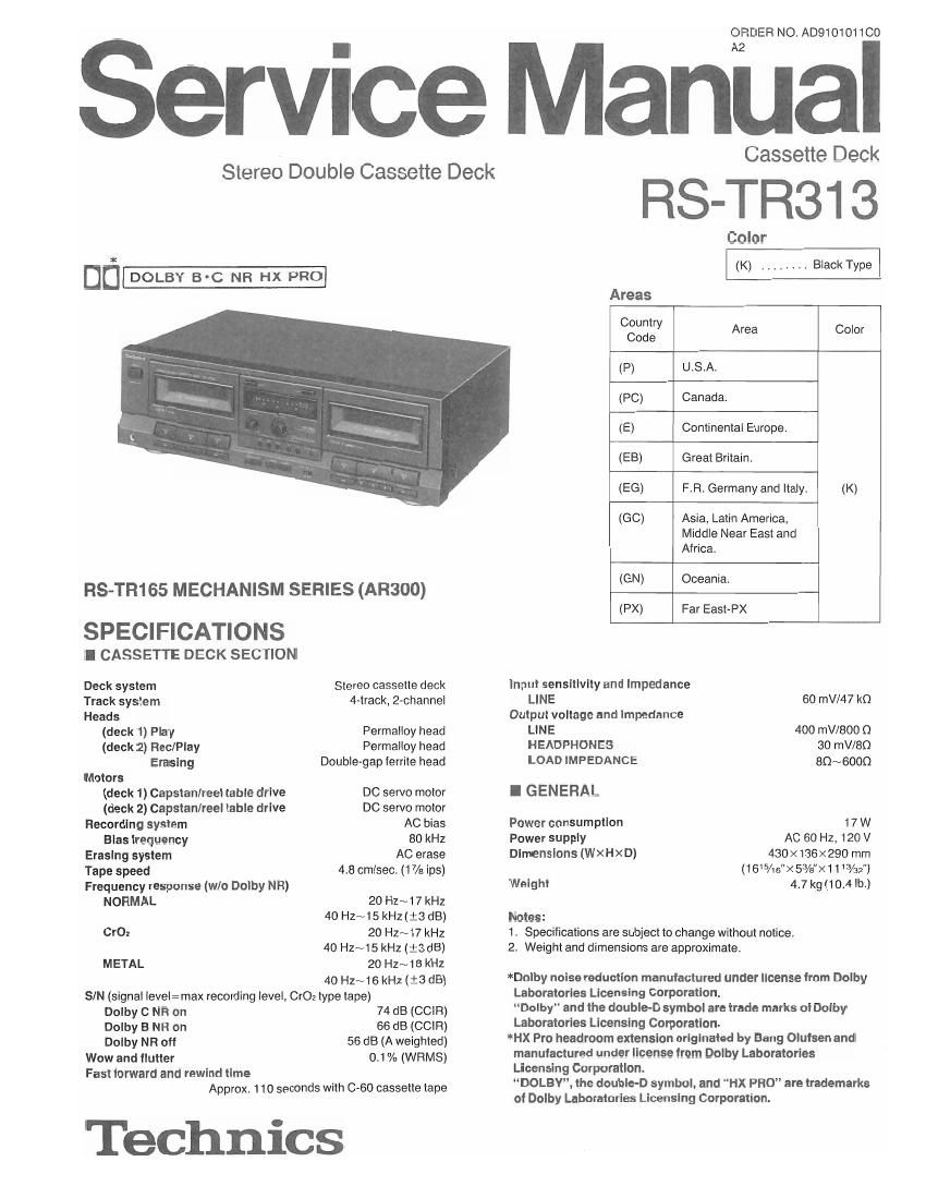
Technics RSTR 313 Service Manual

This is the 26 pages manual for Technics RSTR 313 Service Manual.
Read or download the pdf for free. If you want to contribute, please mail your pdfs to info@audioservicemanuals.com.

Page: 1 / 26
left right
Technics RSTR 313 Service Manual

Extracted text from Technics RSTR 313 Service Manual (Ocr-read)


Page 1

ORDER NO. AD9101011C0

Service Manual

Stereo Double Cassette Deck

DD-

RS-TR165 MECHANISM SERIES (AR300)

SPECIFICATIONS

I CASSETTE DECK SECTION

Deck system
Track system
Heads
(deck 1) Play
(deck 2) Rec/Play
Erasing
Motms
(deck 1) Capstan/reei table drive
(deck 2) Capstan/reel table drive
Recording system
Bias frequency
Erasing system
Tape speed
Frequency response (w/o Dolby NR)
NORMAL

CrOz

METAL

Stereo cassette deck
4~track, 2-channel

Permalloy head
Permalloy head
Double-gap lerrite head

DC servo motor

DC servo motor

AC bias

60 kHz

AC erase

4.8 cm/sec, (17/5 ips)

20 Hz~17 kHz
40 Hz~15 kHz (:3 dB)
20 Hz~17 kHz
40 Hz~t5 kHz (:3 dB)
20 HZ~1B kHz
40 Hz~16 kHz (:3 dB)

S/N (signal level:max recording level, CI'02 type tape)

Dolby C NR on
Dolby B NFI on
Dolby NR oft
Wow and flutter
Fast Iorward and rewind time

74 dB (CCIR)
56 dB (CCIR)

55 as (A weighted)
0.1 % (WRMS)

Approx, 1 10 seconds with C-GO cassette tape

Technics

Cassette Deck

RS-TR31 3

Color
(K) Black Type
Areas 7
Country
Code Area Color
(P) U.S.A.
(PC) Canada.
(E) Continental Europe
(EB) Great Britain
(EG) FR, Germany and itaty. (K)
(GC) Asia. Latin America,
Middle Near East and
Africa.
(GN) Oceania.
(PX) Far East-PX
Input sensitivity and Impedance
LINE 60 mV/47 kn
Output voltage and Impedance
LINE 400 mV/BOO Q
HEADPHONES 30 mV/BQ
LOAD IMPEDANCE 80~6000
I G EN EFIAL
Power consumption 17 W
Power supply AC 60 Hz, 120 V
Dimensions (WXHXD) 430x136><290 mm
(165/15"X 5%")(1 t 3/32)
Weight 4.7 kg (10.4 lb.)

Notes:
1. Specifications are subject to change without notice.
2. Weight and dimensions are approximate.

*Dolby noise reduction manufactured under license Irom Dolby
Laboratories Licensing Corporation.

Dolby" and the double-D symbol are trade marks oi Dolby
Laboratories Licensing Corporation.

*Hx Pro headroom extension originated by Bang Otutsen and
manufactured under license from Dolby Laboratories
Licensing Corporation.

DOLEYY the double-D symbol. and HX PRO" are trademarks
of Dolby Laboratories Licensing Corporation.

Page 2

RS-TR313

I CONTENTS

SAFETY PRECAUTION ,..
ACCESSORIES ,,,,,,,
LOCATION OF CONTROLS .
CONNECTIONS ...........
DISASSEMBLY INSTRUCTIONS ......

MEASUREMENTS AND ADJUSTMENTS ..
BLOCK DIAGRAM
SCHEMATIC DIAGRAM . ..


PRINTED CIRCUIT BOARDS ........................
WIRING CONNECTION DIAGRAM
DESCRIPTION OF FL PANEL

..................... 25

FUNCTIONS OF ic TERMINALS ..

REPLACEMENT PARTS LIST .... ,... . 26~30, 35, 35

MECHANISM PARTS LOCATION (DECK 1) ............ . 31, 32
(DECK 2) .............. 33, 34

CABINET PARTS LOCATION .......................... 37, 38

I SAFETY PRECAUTION (This safety precaution is applied only in U.S.A.)

999?

customer from being exposed to a shock hazard.

oINSULATION RESISTANCE TEST

Before servicing, unplug the power cord to prevent an electric shock,

When replacing parts, use only manufacturers recommended components for safety.

Check the condition of the power cord. Replace if wear or damage is eVIdent.

After semicing, be sure to restore the lead dress, Insulation barries, Insulation papers, shields, etc.

Before returning the serviced equment to the customer, be sure to make the followmg insulation resistance test to prevent the

1. Unplug the power cord and short the two prongs of the plug with a jumperwire.

2. Turn on the power switch.

3. Measure the re5istance value with ohmmeter between the jumpered AC plug and each exposed metal cabinet pan. such as
screwheads antenna, control shafts, handle brackets, etc. Equipment with antenna terminals should read between 3 MO and
5.2 M0 to all exposed parts. (Fig. A) Equipment Without antenna terminals should read approximately Infinity to all exposed

parts. (Fig. B)

Note: Some exposed parts may be isolated from the chassis by design. These will read infinity.

Antenna
terminal

Exposed
maa
pan

Ohmmeter
(Fig. A)
Resistance:3 MQ-5.2 MO

Exposed /L I

metal
part

Ohmmeter
(Fig, Bl
Reststance=Approx. (X)

4. It the measurement is outside the specified limits, there is a possibility of a shock hazard. The equipment should be repaired and

rechecked before it is returned to the customer.

I ACCESSORIES


(SJP2257T) .......
AC | d For remote control cable
(ESE/:3? y cor For synchro edit cable
(SJAt 75-1) )
(SJAT 75) , , )
(SFDACOSEOS). (E, E6)
(SJA193-t) _ _ .(EB) AC plug adaptor
(SJA1 73-1) (GN) (For 60, PX areas only)
(RJAOOO4) .....

Stereo mini cables
........... 2 pcs.

Stereo connection cables
(SJP2249-3) .................... 2 pcs.