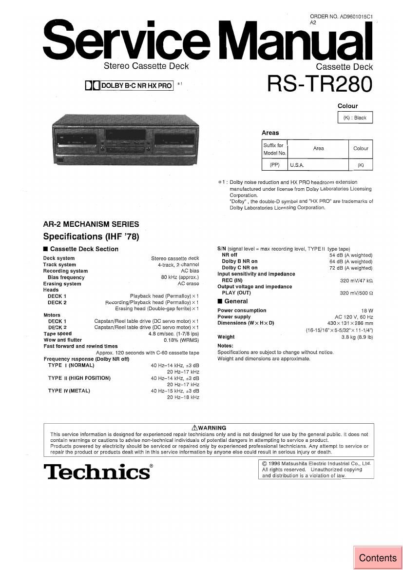
Technics RSTR 280 Service Manual

This is the 58 pages manual for Technics RSTR 280 Service Manual.
Read or download the pdf for free. If you want to contribute, please mail your pdfs to info@audioservicemanuals.com.

Page: 1 / 58
left right
Technics RSTR 280 Service Manual

Extracted text from Technics RSTR 280 Service Manual (Ocr-read)


Page 1

ORDER NO. AD960101501

Service Manual

Stereo Cassette Deck

c_

AR-2 MECHANISM SERIES
Specifications (IHF 78)

I Cassette Deck Section

Deck system Stereo cassette deck
Track system 4-track, 2-channel
Recording system AC bias

Bias frequency 80 kHz (approx)

Erasing system AC erase

Heads
DECK 1 Playback head (Permalloy)><1
DECK 2 Recording/Playback head (Permalloy) X i
Erasing head (Double-gap ferrite) ><1

Motors
DECK 1 Capstan/Fieel table drive (DC servo motor) xi
DECK 2 capstan/Reel table drive (DC servo motor) Xi
Tape speed 4.8 cm/sec. (1-7/8 ips)

Wow and flutter
Fast forward and rewind times
Approx. 120 seconds with 0-60 cassette tape
Frequency response (Dolby NR off)
TYPE I (NORMAL)

0,18% (WFIMS)

40 HZ-14 kHz, :3 dB
20 HZ-17 kHz
40 HZ-i4 kHz, :3 dB
20 HZ-17 kHz
40 HZ-15 kHz. :3 dB
20 Hz-iB kHz

TYPE ll (HIGH POSITION)

TYPE IV (METAL)

Cassette Deck

RS-TR280

Colour
(K) : Black
Areas
Suflix for Area Colour
Model No,
(PP) U.S.A. (K)

*l : Dolby noise reduction and H>< PRO headroom extension
manufactured under license from Dolby Laboratories Licensing
Corporation,

"Dolby" the doubleeD symbol and HX PRO are trademarks of
Dolby Laboratories Licensing Corporation.

S/N (signal level: max recording level. TYFEII type tape)
NR of! 54 dB (A weighted)

Dolby B NR on 64 :15 (A weighted)

Dolby C NFl on 72 dB (A weighted)
Input sensitivity and impedance

FIEC (IN) 320 mV/47 ks:
Output voltage and impedance

PLAY (OUT) 320 mV/SOD $2
I General
Power consumption 18 W

Power supply
Dimensions (WX Hx D)

AC 120 V, 60 HZ
430x 131 X286 mm
(18-15716">< 5-5/32">< i1-1/4")
Weight 3.8 kg (8.9 lb)
Notes:
Specifications are subject to change without notice.
Weight and dimensions are approximate.

AWAHNING
This service information is designed for experienced repair technicians only and is not designed for use by the general public. It does not
contain warnings or cautions to advise non-technical indivrdUais of potential dangers in attempting to service a product,
Products powered by electricity should be serviced or repaired only by experienced professional technicians. Any attempt to service or
repair the product or products dealt with in this service information by anyone else could result in serious injury or death.

Technics®

©1996 Matsushita Electric Industrial 00.. Ltd,
All rights reserved. Unauthorized copying
and distribution is a violation of law.

Contents

Page 2

HS-TFIZBO

l Contents

Safety Precaution .. . 2 Measurements and Adjustments
Front Panel Controls 3 Schematic Diagram
Listening to Tapes . 4 ~ 7 Printed Circuit Board Diagram.
Making a Recording. 8, 9 Wiring Connection Diagram.
Tapeto-Tape Recordin 10. 11 Function oi IC Terminals
To Erase Recorded Sound . .. 11 Block Diagram .....
Service Mode Function of Cassette Mechanism 12, 13 Replacement Parts List

Operation Check and Mechanism Parts Location (Deck 1 52, 53
Main Component Replacement Procedures Mechanism Part5 Location (Deck 2 54, 55
EEPROM Data Write Cabinet Parts Lccatio 56, 57

Adjusted Value Flewri e

I Safety Precaution

1. Before servicing, unplug the power cord to prevent an electric shock.

2. When replacing parts, use only manufacturers recommended components for safety.

3. Check the condition of the power cord. Replace ii wear or damage is evident,

4. After servicing, be sure to restore the lead dress, insulation barriers, insulation papers, shields, etc.

5, Before returning the serviced equipment to the customer, be sure to make the following insulation resistance test to prevent the
customer from being exposed to a shock hazard,

' iNSULATION RESISTANCE TEST

1. Unplug the power cord and short the two prongs of the plug with a jumper wire.

2, Turn on the power switch.

3. Measure the resistance value with ohmmeter between the jumpered AC plug and each exposed metal cabinet part, such as
screwheads antenna, control shafts, handle brackets, etc. Equipment with antenna terminals should read between 3 M9 and
5.2 M9 to all exposed parts, (Fig, A) Equipment without antenna terminals should read approximately infinity to all exposed
parts. (Fig. B)

Note: Some exposed parts may be isolated from the chassis by design. These will read infinity.

Antenna
terminal \
,0
Exposed / Exposed /
metal part melal Pa"
Ohmmeler Ohmmeter
(Fig.Ai (Fig. B)
Resistance = 3 M9 - 5.2 M9 Resistance = Approx. 90

4. If the measurement is outside the specified limits, there is a possibility of a Shock hazard. The equipment should be repaired
and rechecked before it is returned to the customer.

Page 12

RS-TFI2BO

l Service Mode Function of Cassette Mechanism

This unit is equipped with a self-check mode of its cassette mechanisms using the display at diagnostic items.
As the mode is capable ot identitying the laults described below, make the most of it when servicing the unit.

a Cassette tapes to be prepared
Normal blank tape with only one erase-prevention tab intact (use middle portion of tape).
Normal blank tape with both erase-prevention tabs intact (use middle portion of tape).

0 Selecting Service Mode

0 Deck 1 Mechanism Check

Turn on the power to the unit.

Check that no tape is inserted in the cassette deck.
Press the DOLBY NR button for about 2 seconds, and
keep pressing it, also press the STOP button for about
2 seconds. (Wrong result is occurred if any tape is
inserted. To clear it, press STOP button lot more than
6 seconds.)

The level meter changes from constantly lit to blinking,
the service mode has been activated.

[When activated, this mode checks that the following
mechanism switches (MODE detect, REC prevention,
Halt detect, Cr02 tape detect, Metal tape detect) are
OFF].

Press the DECK 1/2 button to display DECK 1. (It
DECK 1 is already displayed, no selection is made.)

Open the Deck 1 cassette holder.

(OPEN button)

Load the DECK 1 cassette holder with a normal blank
tape with only one erase-prevention tab intact and close
it.

Press the PLAY b button. After about 2 seconds, then
press the STOP l button. (During this period, the mode
checks the Cr02 and metal tape detect switches are
ON and the REC prevention switch remains OFF.)

Open the Deck 1 cassette holder.

(OPEN button)
Tofi

-12-

POWER

El

DOLBY NFI STOP
g D

DECK 2 E 2 m.

\llllllllllllllllllllll I
\L

_dB-2o --15 40.5 4 0 +2
/R
llllllllllllllllllllllll

l>

OPEN