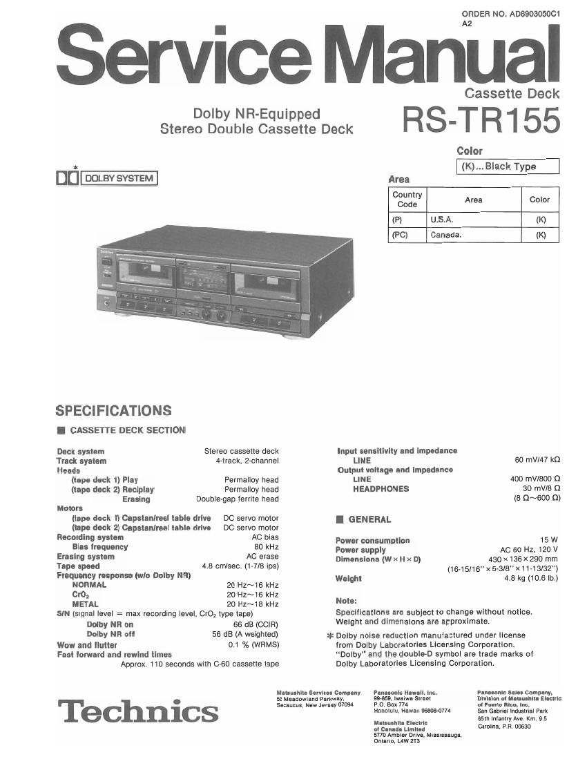
Technics RSTR 155 Service Manual

This is the 34 pages manual for Technics RSTR 155 Service Manual.
Read or download the pdf for free. If you want to contribute, please mail your pdfs to info@audioservicemanuals.com.

Page: 1 / 34
left right
Technics RSTR 155 Service Manual

Extracted text from Technics RSTR 155 Service Manual (Ocr-read)


Page 1

ORDER NO. A08903050C1

Service ManUal

Dolby NR-Equipped
Stereo Double Cassette Deck

SPECIFICATIONS
I CASSETTE DECK SECTION
Deck system Stereo cassette deck
Track system 4-track, 2-channel
Heads
(tape deck 1) Play Permalloy head
(tape deck 2) Reclpley Permalloy head
Erasing Doublegap ferrite head
Motors

(tape deck 1) Capstenlreel table drive DC servo motor
(tape deck 2) Cepstenlroel table drive DC servo motor

Recording system AC bias
Bias iroquency 80 kHz
Erasing system AC erase
Tape speed 4.8 cm/sec. (1»7/8 ips)
Frequency response (wlo Dolby NR)
NORMAL 20 HZ~16 kHz
mo. 20 Hz~16 kHz
METAL 20 Hz~18 kHz
SIN (signal level = max recording level, CrOz type tape)
Dolby NR on 66 dB (com)
Dolby NR oil 56 dB (A weighted)
Wow and flutter 0.1 % (WRMS)

Fest lorward and rewind times
Approx. 110 seconds with C-60 cassette tape

Mmumu service- Comp-n1 Pun-conic Haw-Ii. inc.

Cassette Deck

RS-TR155

Color
(K)... Black Type

Area
Country
Code Area Color
(P) U.S.A. (K)
(PC) Canada. (K)
Input sensitivity and Impedance
LINE 6O mV/47 kn
Output voltage and Impedance
LINE 400 mV/800 Q
HEADPHONES 30 mV/8 Q
(8 Q~600 Q)
I GENERAL
Power consumption 15 W
Power supply AC 60 Hz, 120 V

Dimensions (w x H x D) 430 x 136 X 290 mm
(16-15l16" x 5<3l8"x11-13l32")

Weight 4.8 kg (10.6 lb.)

Note:

Specifications are subiect to change without notice.
Weight and dimensions are approximate.

* Dolby noise reduction manufactured under license

from Dolby Laboratories Licensing Corporation.
Dolby" and the double-D symbol are trade marks of
Dolby Laboratories Licensing Corporation.

FInuonle sun Company,

. 50 Meadowiand Parkway, 99859. Iwniwa Street DIVIIIOII 0 MIHMIMM Ella":
Secaucus. New Jamey 07094 P.O. BOX 774 nl FIRM Rico, inc.
Honolulu. Hawaii 9660H774 San Gabriel industrial Park
65th lnlantry Ave. Km. 9.5

Zatt'flfiimfi Carolina. P.R. 00630

5770 Ambler Drive, Mlselssaugl.
Onteno. L4W Zia

Page 2

RS-TR155

I CONTENTS

oSafety Precaution ..
nAccessories .........

0 How To Connection..
~Locatlon of Controls
oDisassembly instructions.
'Measurement and Adjustment Methodes.
'Terminal Function of lCs ........................
~Prlnted Circuit Boards.
-Schemat|c Diagram ......


Page

cTerminaI Guide of lCs,
Transistors and Diodes ................................... 25
OBlock Diagram ........................
OWiring Connection Diagram.
0 Resistors & Capacitors ......
OReplacement Parts List (Eiectrical Parts)
nMechanical Parts Location (DECK 1) ........
- Replacement Parts List
(Mechanical Parts) ......................
OMechanical Parts Location (DECK 2
OCabinet Parts Location ............................
OFteplacemant Parts List (Cabinet Parts)

I SAFETY PRECAUTION (This safety precaution" ls applied only in USA.)

mwa

o INSULATION RESISTANCE TEST

, Before servicing, unplug the power cord to prevent an electric shock.

. When replacing parts, use only manufacturers recommended components for safety.

. Check the condition of the power cord. Replace if wear or damage is evident.

. After servicing, be sure to restore the lead dress, insulation barriers, insulation papers, shields, etc.
Before returning the serviced equipment to the customer, be sure to make the following Insulation resistance test to
prevent the customer from being exposed to a shock hazard.

l. Unplug the power cord and short the two prongs of the plug with a jumper wire.

2. Turn on the power switch.

3. Measure the resistance value with ohmmeter between the iumpered AC plug and each exposed metal cabinet part, such as
screwheads antenna, control shafts, handle brackets, etc. Equipment wrth antenna terminals should read between 3M0.
and 5.2MQ to all exposed parts, (Fig. A) Equipment without antenna terminals should read approximately infinity to

all exposed parts. (Fig. 8)
Note:

Antenna
termlnal \

Exposed
metal
part

Ohmmeter

(Fig.AI

Resistance = 3 MQ-5.2 M9

Some exposed parts may be isolated from the chassis by design. These will read infinity,

Exposed , 5
metal
part
Ohmmeter
(Fig.3)

Resistance = Approx 00

4. lf the measurement is outside the specified limits, there IS a possrbility of a shock hazard. The equipment should be

repaired and rechecked before it is returned to the customer