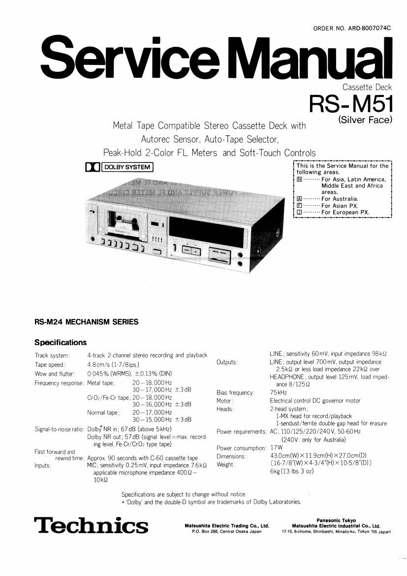
Technics RSM 51 Service Manual

This is the 26 pages manual for Technics RSM 51 Service Manual.
Read or download the pdf for free. If you want to contribute, please mail your pdfs to info@audioservicemanuals.com.

Page: 1 / 26
left right
Technics RSM 51 Service Manual

Extracted text from Technics RSM 51 Service Manual (Ocr-read)


Page 1

ORDER NO. ARD-8007074C

Service Manual

Cassette Deck

RS-M51

Metal Tape Compatible Stereo Cassette Deck with (Silver Face)

Autorec Sensor, AutorTape Selector,
PeakeHold 2~Co|or FL Meters and Soft-Touch Controls

m DOLBY SYSTEM This is the Service Manual for the

following areas,

--------- For Asia, Latin America,
Middle East and Africa
areas.

El ......... For Australia.
[E] .. 'For Asian PX.
III ttttttttt For European PX.

RS-M24 MECHANISM SERIES

Specifications
Track system detrack 2Achannel stereo recording and playback LlNE; seriSitii/ity 60 mV, input impedance 98 kg
Tape speed 4 Born/s (1'7/8li35) Outputs' LlNE; output level 700 mV, output impedance
' ' 2,5k52 or less load impedance 22 k9 over
. + 0
WW and my 0 045% lWRMSl *013 /° (D'Nl HEADPHONE, output level 125 mV. load impede
Frequency response' Metal tape, 20 18,000 Hz + ance 8/12582
C O, 'F C t $712883 S2 3dB Bias frequency 75kHz
r i/ e- r ape, 3O--16IOOOH: +3dB Motor Electrical control DC governor motor
7 i 7 Heads 27head system,
Normal tape, ggigggg :: i3dB 1-MX head for record/playback

lrsendust/territe doublergap head for erasure
Power requirements AC, 110/125/220/240 V, 50760 Hz
(240V. only tor Australia)
Power consumption 17W

Signal-toenOise ratio Dolbf NR in; 67 dB (above 5kHz)
Dolby NR out; 57dB (Signal level:max record
ing level, FevCr/Cr02 type tape)
Fast forward and

rewind time Approx 90 seconds With 060 cassette tape Dimemlons {l3 OchN) X11.9cm(l-l) X27.0cmSD)
lnputs MlC, sensitiwty 0,25mV, input impedance 7 6kg} Weight k16'7/8 (W) X4r3/4 (H)><1075/8 (D)]
applicable microphone impedance 40097 6kgl13 lbs 3 OZ)
10k§2

Specifications are subiect to change Without notice
r 'Dolby and the doublerD symbol are trademarks ot Dolby Laboratories.

. Panasnnli: Tokyo
ec nlcs Mllsushila Electrlc Tradlng Co., Ltd. Matsushlta Electrlc lndustrlul 00., Ltd.
P.O. Box 288, Central Osaka Japan 17-15. 6-chome. Shrnbashl, Minalo-ku, Tokyo 05 Japan

Page 2

RS-M51

CONTENTS

ITEM
LOCATION OF CONTROLS AND COMPONENTS -------------------

DISASSEMBLY INSTRUCTIONS .............................................................. 2
DISASSEMBLY NOTES (MECHANISM UNIT) ............................................ 3
ASSEMBLY INSTRUCTIONS .................................................................. 4
OPERATING PRINCIPLE OF AUTOMATIC INPUT CHANGEOVER MECHANISM -------------------------------- 6
TECHNICAL INFORMATION OF AUTO-REC SENSOR .................................................................... 7

MEASUREMENT AND ADJUSTMENT METHODS --------------------------------------
SCHEMATIC DIAGRAM (MAIN AMP AND DIGITAL VR SECTION) ---------------

CIRCUIT BOARDS (MAIN AMP AND EQUALIZER CIRCUIT BOARD) .............................................. 14
SCHEMATIC DIAGRAM (DIGITAL VR CONTROL, POWER SUPPLY AND FL METER SECTION) ---------- 15
CIRCUIT BOARDS (DIGITAL VR CONTROL POWER SUPPLY AND FL METER CIRCUIT BOARD) ~~~~~~~ 16
ELECTR|CAL PARTS LOCAT|0N ................................................................................................ 16
WIRING CONNECTION DIAGRAM ------------------------ 17
MECHANICAL PARTS LOCATION ........................ 18
CAB|NET PARTS ..................................................................................................................... 19

LOCATION OF CONTROLS
AND COMPONENTS

@ @ ® 29 ®
Ell
® Power switch (power) @ Pause button (|| pause)
® Cassette holder Record-muting button (rec mule)
© Tape selector indicators (normallCrOleetal/Fe-Cr) ® Dolby noise-reduction switch (Dolby NR)
(9 Tape counter and Reset button (tape counter) ® Recording level variation button
(5) Microphone indicator (mic) [level llne adlust (downlup)]
Dolby noise reduction indicator (Dolby NR) @ Recording level detection indicalor (search)
® Recording indicator (rec) @ Recording level automatic selling button
® Recording level setting indicator [autorec sensor (autorec level sensor)]
(level sensor read-oul) ® Recording level setting complete indicator (level sel)
® FL (fluorescent level) meters @ Microphone lacks (L mic R)
Headphones jack (phones) @ Output level control (OUTPUT LEVEL)
® Eject button (A eiecl) ® Remotecontrol conneclor (REMOTE CONTROL)
® Record button (0 rec) @ Lille output iaclts (LINE OUT) (R - L)
® Rewind/Review button (44 rewlrev) @ Line input jacks (LINE m) (R . L)
@ Fasl forward/Cue button (b) "/cue) @ Tape selector [tape select -(MetaIICrOzInormal)/
@ Play button (} play) (Fe-CrIMelal)]
® Slop button (I slop) @ Voltage selector (VOLTAGE SELECTOR)
(- ----- For PX. )
IE] --------- For Asia, Latin America, Middle East and Africa areas.