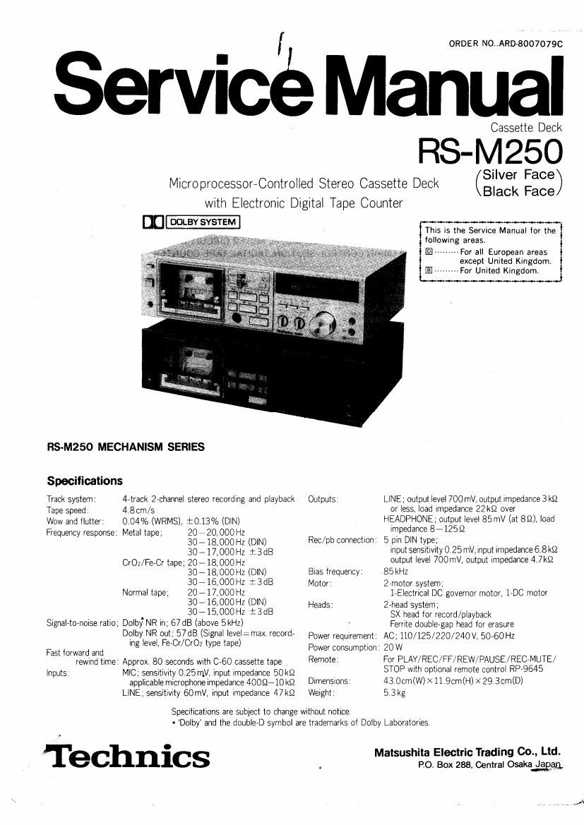
Technics RSM 250 Service Manual

This is the 27 pages manual for Technics RSM 250 Service Manual.
Read or download the pdf for free. If you want to contribute, please mail your pdfs to info@audioservicemanuals.com.

Page: 1 / 27
left right
Technics RSM 250 Service Manual

Extracted text from Technics RSM 250 Service Manual (Ocr-read)


Page 1

ORDER NO .ARD- 80070790

Service Manual

Microprocessor-Controlled Stereo Cassette Deck
with Electronic Digital Tape Counter

m 00st SYSTEM

RS-M250 MECHANISM SERIES

Specifications

Track system: 4-track Zechannel stereo recording and playback
Tape speed: 4t8crn/s
Wow and flutter: 0.04% (WRMS), i0.13% (DIN)
Frequency response: Metal tape; 20 v7 20,000 Hz
30 7 18, 000 Hz (DIN)
30-17,OOOH2 :3dl3
CrO2/Fe-Cr tape; 20 - 18,000 Hz
30718000 Hz (DIN)
30- 16,000 Hz 1".3dB
Normal tape; 20- 17,000 Hz
30- 16,000 Hz (DIN)
30715,000Hz :3dB
Signaletoenoise ratio; Dolby. NR in; 67 dB (above 5kHz)
Dolby NR out; 57dB (Signal level: max record-
ing level, Fe Cr/CrOz type tape)
Fast forward and
rewrnd time: Approx. 80 seconds With C-6O cassette tape .
Inputs: MIC; sensitivity 0 25 mV, input impedance 50k$2
applicable microphone impedance 40052710 k0
LINE; sensitivity 60mV, input impedance 47k§2

Outputs:

Rec/pp connection:

Bias frequency:
Motor:

Heads:

Power requirement:

Cassette Deck

RS-M250

(Silver Face)
Black Face

This is the Service Manual for the
following areas,

El --------- For all European areas
except United Kingdom.
-------- For United Kingdom.

LINE: output level 700 mV, output impedance 3 kt!
or less, load impedance 22kt} over
HEADPHONE: output level 85 mV (at 8S2), load
impedance 8 7125 Q
5 pin DlN type;
input sensitivity 0, 25 mV, input impedance 6.8 ktz
output level 700 mV, output impedance 4.7k52
85 kHz
27-motor system,
1~Electrica| DC governor motor, 1-DC motor
2-heacl system;
SX head tor record/playback
Ferrite doublegap head Ior erasure
AC; 110/125/220/240 V, 50-60 Hz

Power consumption: 20 W

Remote:

Dimensions
Weight:

Specifications are subject to change without notice
. Dolby and the double-D symbol are trademarks of Dolby Laboratories

Technics

For PLAY/REC/FF/ REW/PAUSE/REGMUTE/
STOP with optional remote control RP~9645

43 Ocrn(W)X11.9r:m(H)>< 29 3cm(D)
53kg

Matsushita Electric Trading Co., Ltd.
PO. Box 288. Central Osaka £33333;

Page 2

' S-M250 ' ,

CONTENTS

ITEM
LOCATION OF CONTROLS AND COMPONENTS ------------------------------------
DISASSEMBLY INSTRUCTIONS -------------------------
MEASUREMENT AND ADJUSTMENT METHODS~

MN14OORS: TERMINATION BOTTOM VIEW ----------------------------------------------- 7
MN14OORS: EACH TERMINAL FUNCTION AND WAVEFORM-- 8
TROUBLESHOOTING .................... 12
ELECTRICAL PARTs LOCATION - 13
SCHEMATIC DIAGRAM (MAIN AMP SECTION) ------------------------------------------- 15
CIRCUIT BOARDS (MAIN AMP CIRCUIT BOARD, FL METER CIRCUIT BOARD) 16
SCHEMATIC DIAGRAM (MAIN CONTROL SECTION, DIGITAL TAPE COUNTER

DRIVE SECTION) ............................................................................................. 17
CIRCUIT BOARDS (MAIN CONTROL CIRCUIT BOARD, DIGITAL TAPE COUNTER


DRIVE CIRCUIT BOARD, CONTROL KEY SWITCH CIRCUIT BOARD) ----------------------- 18
MECHANISM EXPLODED VIEWS ------
WIRING CONNECTION DIAGRAM ~-
MECHANISM PARTS LOCATION
CABINET PARTS ................................................................................................ 21

LOCATION OF CONTROLS
AND COMPONENTS

(D Power switch [power (push on)[
.@ Eiecl button (eject)
® Cassette holder
{0 Remaining tape display light
© Head light
Tlmer start switch [[Qtlmer (rec-ott-play)]
(D Memory switch [memory (stop-ott-play-repeatn
® Reset button (counter reset)
Dlgltal tape counter (tape counter)
® FL (tluorescent level) meters
@ Microphone lacks [mlc (leitrlghtn
62) Input level controls [input level (L -§)-H)]
® Dolby noise reduction switch
[Dolby NR (.lout- :Inn
® Tape selector
[tape select (nor-Fe-Cr-CrOz-Melaln
® Multiplex tllter switch [MPX tiller (1 out. .- In)]
Q9 Output level control (output level)
® Input selector [Input select ( lline-l mlc) (DIN)]
® Record-muting button (rec mute)
@ Fast torwerd button (b) It)
Q Stop button (I stop)
{9 Remote-control connector (remote)
@ Play button[Playback-indication lamp ( [>play)
@ Rewlnd button ((4 rew)
® Pause button/Peuse-lndlcalicn lamp (0 pause)
@ Record butloanecord-indicatlon lamp (0 rec)
@ Headphones lack (phones)
@ Line output jacks (LINE OUT) (R, L)
@ Record/Playback connection socket (REC/PB)
® Line Input jacks (LINE IN) (R, L)
® Voltage selector (VOLTAGE SELECTOR)

Page 23

f

Mi RS-M250 RS-M250

mumm'asww...

C 003V
5 0.81V
E 0V


0:02v
0v

E
0303

0304 Q
28D636(S R Q) 2806366 R Q) 28D636(S R Q)

NOTES:

0 The circuit shown in - on the conductor is +B (bias) Circuit.

0 The circuit shown in fin » on the conductor Indicates printed circuit, which is
included printed type istovs.

OThe circuit shown in M 151; on the conductor Indicates printed circuit on the back
side at the printed circuit board.

OThe symbols (0) indicate connection points between conductors on the hunt side
and back side of the circuit board.

OValues indicated in I: ave DC voltage between the ground and electrical parts.

0312, 313

288835 (T, S, Fl)
5.4 v
545v
545v

B
E

0314, 315
280965 (S, R, Q)

C C 5.45V
B , B . V
E 0V E 0V
M0316 317

28 D638 (8, R)


To Meter
Gaunt!
Circu
Bail V

.26.25.24.23.22.21.20.19.18.17.16.15.14.13L12.li.10.9.8.7.6.5.4.3.2.1
DkilTeAtiEéfiiTcééEJER
D
CIRCUIT BOARD _, ,_ 1
MAIN CONTROL CIRCUIT BOARD
; Tanrgiy
' a w : |CSO1 5312??
5 5 ~ M N14OORS 5""11 _
1 « _
5 0.02V W,
18-2 5. To Ecntmlf
27 531 13:3)
28- 5. V ' g'
L 39 5.35V i
i . it;
) 3 ;