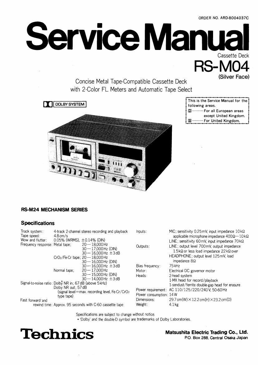
Technics RSM 04 Service Manual

This is the 24 pages manual for Technics RSM 04 Service Manual.
Read or download the pdf for free. If you want to contribute, please mail your pdfs to info@audioservicemanuals.com.

Page: 1 / 24
left right
Technics RSM 04 Service Manual

Extracted text from Technics RSM 04 Service Manual (Ocr-read)


Page 1

ORDER NO, ARD-8004037C

Service Manual

Cassette Deck

RS- M04

. . (Silver Face)
ConCIse Metal Tape-Compatible Cassette Deck

with 2-Color FL Meters and Automatic Tape Select

This is the Service Manual for the
m- following areas.
In --------- For all European areas
except United Kingdom
For United Kingdom.
RS-M24 MECHANISM SERIES
Specifications
Track system: 4-track 2-channel stereo recording and playback inputs: MIC; sensitivity 0.25mV, input impedance 10k52
Tape speed: 48 cm/s applicable microphone impedance 4009- 10 k9
Wow and flutter: 0.05% (WRMS), i0.14% (DIN) LlNE; sensitivity 60mV, input impedance 70 k9
Frequency response: Metal tape; 58 : $888 :2 (DIN) Outputs: LINE; output level 700 mV, output impedance
30 -16000 H: + 3 dB 1.5 kg or less load impedance 22 k9 over
CrOz/Fe-Cr tape; 20-18JOOOHZ HEADPHONE; output level 125mV, load
30-16,000HZ (DlNl Impedance 89
30-16,000Hz i3dB Bias frequency: 75kHz
Normal tape; 20-17000 Hz Motor: Electrical DC governor motor
30 15900 HZ (DlN) Heads: 2Ahead system
30- 14900 HZ : 3 dB 1-MX head for record/ playback

Signal-to-noise ratio: Dolby NR in; 67 dB (above 5kHz)
Dolby NR out; 57 dB
(signal level:max. recording level, Fe-Cr/Cr02

1-sendust/ierrite double-gap head for erasure
Power requirement: AC 110/125/220/240 V, 50-60 Hz

type tape) Power consumption: 14 W
Fast forward and Dimensions: 29.7cm(W)><12:2cm(H)><23.2 cm(D)
rewind time: Approx 95 seconds with 0-60 cassette tape Weight: 4.1 kg

Specifications are subject to change without notice.
- Dolby and the double-D symbol are trademarks of Dolby Laboratories.

h' E ' ' 00., Ltd.
Technlcs M°°°° 2.2 '22::12222mm

Page 2

RS-MO4

CONTENTS

ITEM PAGE
LOCATION OF CONTROLS AND COMPONENTS ......................................................... 1
DISASSEMBLY INSTRUCTIONS ............................................................................... 2
DISASSEMBLY NOTES (MECHANISM UNIT) ............................................................. 3
ASSEMBLY INSTRUCTIONS .................................................................................... 3
CIRCUIT BOARDS AND ADJUSTMENT PARTS LOCATION ------------------------------------------ 6
MEASUREMENT AND ADJUSTMENT METHODS ------------------------------------------------------ 7


ELECTRICAL PARTS LOCATION ---------
SCHEMATIC DIAGRAM -----
CIRCUIT BOARDS ...........
WIRING CONNECTION DIAGRAM -------------

EXPLODED VIEWS ................................................................................................. 15
MECHAN'CAL PARTS LOCATION ............................................................................ 16
CABINET PARTS ................................................................................................... 17

LOCATION OF CONTROLS
AND COMPONENTS

Q0 0
CD ® @ GD ® ® @ (D Power swltch (power)
I .1 ® Cassette holder
i - m . © Microphone Indicator (mic)
o J: I "" " '5' © Dolby nolse reductlon Indicator (lilolby NR)
1 _ . I m (E Recording indicator (rec)
_ - _ £1 fifl * Tepe counter and Reset button (tape counter reset)
4%,. ...... I. am, j (7) Tape selector Indicators (norlCrOJMetel/Fe-Cr)
"W""" 73 3g '- _,, FL (fluorescent level) meters
m W71;- ,...I ._ . w (9 Input level controls (Input level) (L ~9- R)
? a "I CT {3" E: m LT. ?*? @ ® Headphones Ieok(phones)
__ ® Eject button (; eject)
I l"I" @ Record button (0 rec)
® ® ® ® ® ® ® RewindIl-Ievlew button ( < 4 rewlrev)
10 ® ® db ® ® ® Fast forward/Cue button ( V D Illcue)

® Play button ( D ploy)
® Stop button (I stop)

® Pause button ( || pause)
® ® @ ® Tune selector (music select)

69 Record-muting button (rec mute)
l I ® Dolby nolee-reductlon switch (Dolby NR)
® Microphone jacks (L mic R)
@ Output level control (output level)

® Llne output jacks (LINE OUT) ( R- L)
(8 Line Input lacks (LINE IN) (R t L)

l I ® Tepe selector
,9 mo) Q LMQ- \ (Fe-CrIMeteII nor/CrOJMetall )
mm I. .I 233mm..." I 69 Voltage selector (VOLTAGE SELECTOR)
- -I
Fig. I