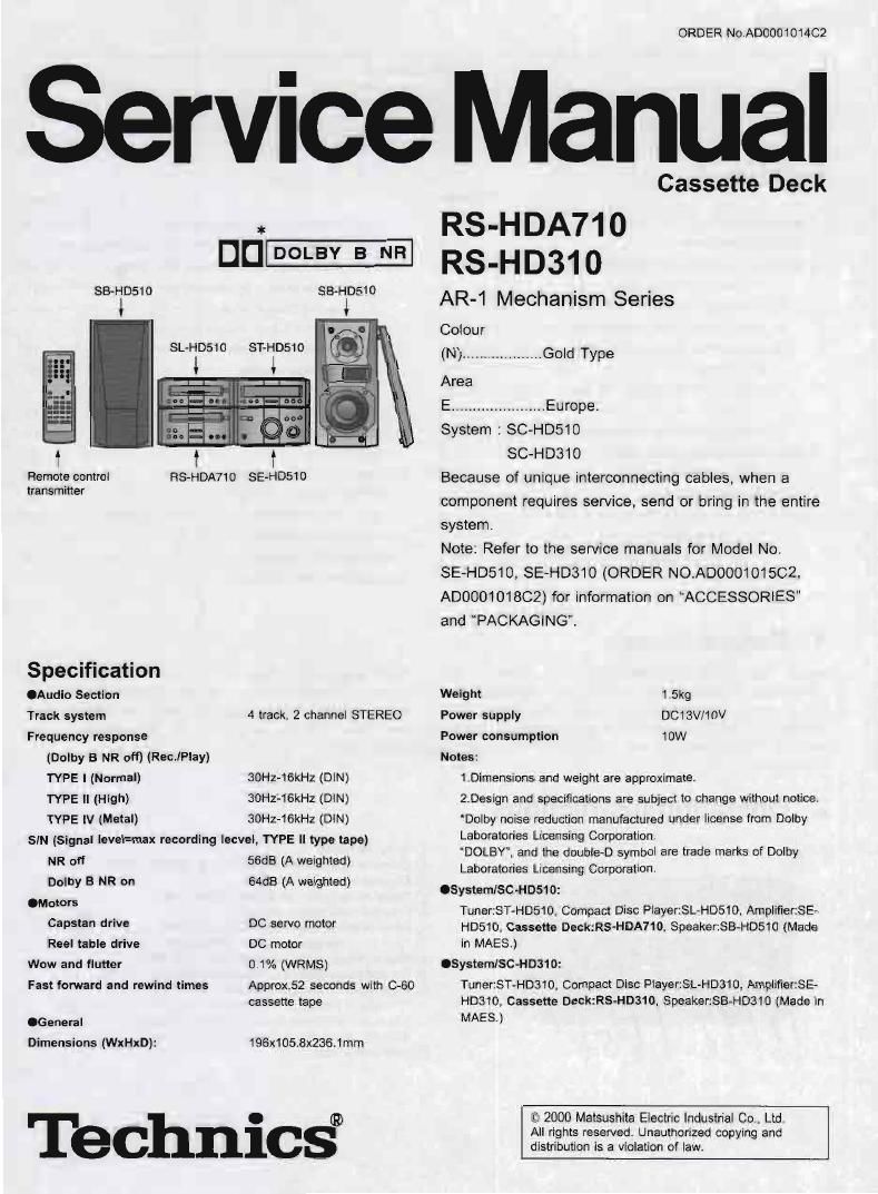
Technics RSHDA 710 Service Manual

This is the 32 pages manual for Technics RSHDA 710 Service Manual.
Read or download the pdf for free. If you want to contribute, please mail your pdfs to info@audioservicemanuals.com.

Page: 1 / 32
left right
Technics RSHDA 710 Service Manual

Extracted text from Technics RSHDA 710 Service Manual (Ocr-read)


Page 1

ORDER No ADGOOWOMCZ

Service Manual

a:
DD DOLBY B NR
SB-HDSIO SB-HD510
SL-HDS10 ST-HDStO

l l

i :2.

i l

RS-HDA710 SE-HDS10

Remote control
trans mitter

Specification
.Audio Section
Track system 4 track. 2 channel STEREO
Frequency response
(Dolby B NR off) {Rem/Play)
TYPE I (Normal) 30Hz-16kHz (DiN)
TYPE ll (High) 30H2-16kHz (DiN)
TYPE lV (Metal) 30HZ-16kHz (DIN)

SIN (Signal level=max recording lecvel, TYPE ll type tape)

NR oft 56dB (A weighted)
Dolby 3 NR on 64:13 (A weighted)
.Motors
Capstan drive DC servo motor
Reel table drive DC motor
Wow and flutter 0 1% (WRMS)

Approx.52 seconds with (3-60
cassette tape

Fast forward and rewind limes

.General

Dimensions (WxHxD): 196x105.8x236.1mm

Tbchnics

Cassette Deck

RS-HDA71O
RS-HD310

AR-1 Mechanism Series

Colour

(N) ................... Gold Type

Area

E. ..Europe.

System : SC-HDStO
SC-HD310

Because of unique interconnecting cables, when a
component requires service, send or bring in the entire
system.

Note: Refer to the service manuals for Model No.
SE-HD510, SE-HD310 (ORDER N0.A00001015C2,
AD000101802) for information on "ACCESSORlES"
and PACKAGING".

Weight 1 5kg
Power supply DCtBV/10V
Power consumption 10W
Notes:

1 Dimensions and weight are approximate.
2.Design and specifications are subject to change without notice.
'Dclby noise reduction manufactured under license from Dolby
Laboratories Licensing Corporation.
DOLBY. and the double-D symbol are trade marks at Dolby
Laboratories Licensing Corporation.

ISystem/SC-HD510:
Tuner:ST-H0510. Compact Disc Piayer:SL-HDSlO. Amplifier:SE-
HD510, Cassette DecszS-HDAH 0, Speakersz-HDstu (Made
in MAES.)

.SystemlSC-HD310:
Tuner:ST-HD310, Compact Disc Piayer:SL-HD310, Amplifierst-
H0310, Cassette Deck:RS-HD310, Speaker:SB-H0310 (Made in
MAES.)

I. 2000 Matsushita Electric Industrial Co., Ltd.
All rights reserved. Unauthorized copying and
distribution is a violation of law.

Page 2

HSHDAHD l PIS-HUSH)

A WARNING

This service information is designed tor experienced repair technicians only and is not designed for use by the general public.

It does not contain warnings or cautions to advise non-technical individuals of potential dangers in attempting to service a product.
Products powered by electricity should be serviced or repaired only by experienced professional technicians. Any attempt to service
or repair the product or products dealt with in this service information by anyone else could result in serious injury or death.

CONTENTS

1 Before Repair-


2 Operating Instruc ons
3 Operation Checks and Component Replacement Procedureso
3.1. Checking for the operation P.C,B. ----------------------------------- 3
3.2. Checking for the main P.C.B. rrrrrrrrrrrrrrrr
33. Replacement for the cassette holder assy

34. Replacement for the belt, reel motor assy and capstan
motor assy ------------------------------------------------------------------ 5
3.5, Replacement for the pans mounted on mechanism P.C.B.

3.6. Replacement tor the head block and pinch roller assy
4 Measurements and Adiustments -------------------------------------------- B
4.1. To Supply Power Source ------------------------------------------------ 8
4.2. To Check Signals --------
4.3. Head Azimuth Adjustmen
4.4. Tape Speed Adjustment-
4.5. Playback Gain Adiustment -------------------------------------------- 9

4,6. Erase Current Confirmation ------------------------------------------- 9

1 Before Repair

These equipments (RS-HDA710/HD310), which are
components of these systems, are supplied with power from
the amplifiers (SE-HD510/310) through the tuners (ST-
HD510/310) When repairing these equipments or checking
operation of the systems. be sure to connect the amplifiers and
tuners with it.

2 Operating Instructions

4.7. Playback frequency response check *-
4.8. Recording/playback frequency response and gain check-10

5 Semice Mode Function 01 Cassette Mechanism ------------------ 11
5.1 Cassette tapes to be prepared ...................................... 11
5.2. Selecting Service Mode 11
5.3. Exiting Sell-Check Mode 12
6 Wiring Connection Diagram rrrrrrrrrrrrrrrrrrrrrrrrrrrrrrrrrrrrrrrrrrrrrrrrr 13
7 Schematic Diagram Notes ---------------------------------------------------- 14

7.1. Type Illustration 0! lCs. Transistors and Diodes
7.2. Schematic Diagram Notes-

8 Schematic Diagram rrrrrrrrrrrrrrrr
9 Block Diagram ---------------------------------------------------------------------- 20
10 Printed Circuit Board Diagram ---------------------------------------------- 22
11 Terminal Function of lC's ---------------------------------
11.1. lC7OT(M37478M4458F): SYSTEM CONTROL
12 Replacement Parts List -----------------------------------------
13 Cabinet Parts Location rrrrrrrrrrrrrrrrrrrrrrrrrrrrrrrrrrrrrrrrrrrrrrrrrrrrrrrr 30

14 Mechanism Parts Location --------------------------------------------------- 31

These equipments. even in the state of it as a single
equipment, permits power supply and operation check. When
operating it as a single equipment without the amplifier and
tuner, refer to the paragraph of Measurements and
Adjustments.

® Cassette holder

(2) Cassette tray open/close button (A OPEN/CLOSE)
[:9 Counter button (COUNTER)

3 Dolby noise reduction button (DOLBY NR)

é) Counter reset button (RESET)

Reverse mode select button (REV MODE)

® Tape Program Sensor button (TPS SKIP)

® Fast forward/rewind buttons ((4 [TPS] >>)

(it) Record pause button and indicator (0 REC PAUSE)

it? Playback buttons and indicators ("i ')
The color ot the indicator depends on the operation taking place.
If stopped fast forwarding or reWinding: orange
If playing. recording, or carrying out TFS: green

® Stop button (I)

Page 7

3.6. Replacement for the head
block and pinch roller assy
- Follow the (Step 1) - (Step 5) of item 3.7.
. Follow the (Step 1) - (Step 8) of item 3.3.
- Follow the (Step 1) - (Step 5) of item 3.4.
Step 1)

elease the 2 claws, and then
remove the plrlCh roller ass'y.

Pinch roller
(R) assy

Pinch roller
(F) assy

EStep 2)
emove the connector holder.

RS-HDAIW (RS-H0310