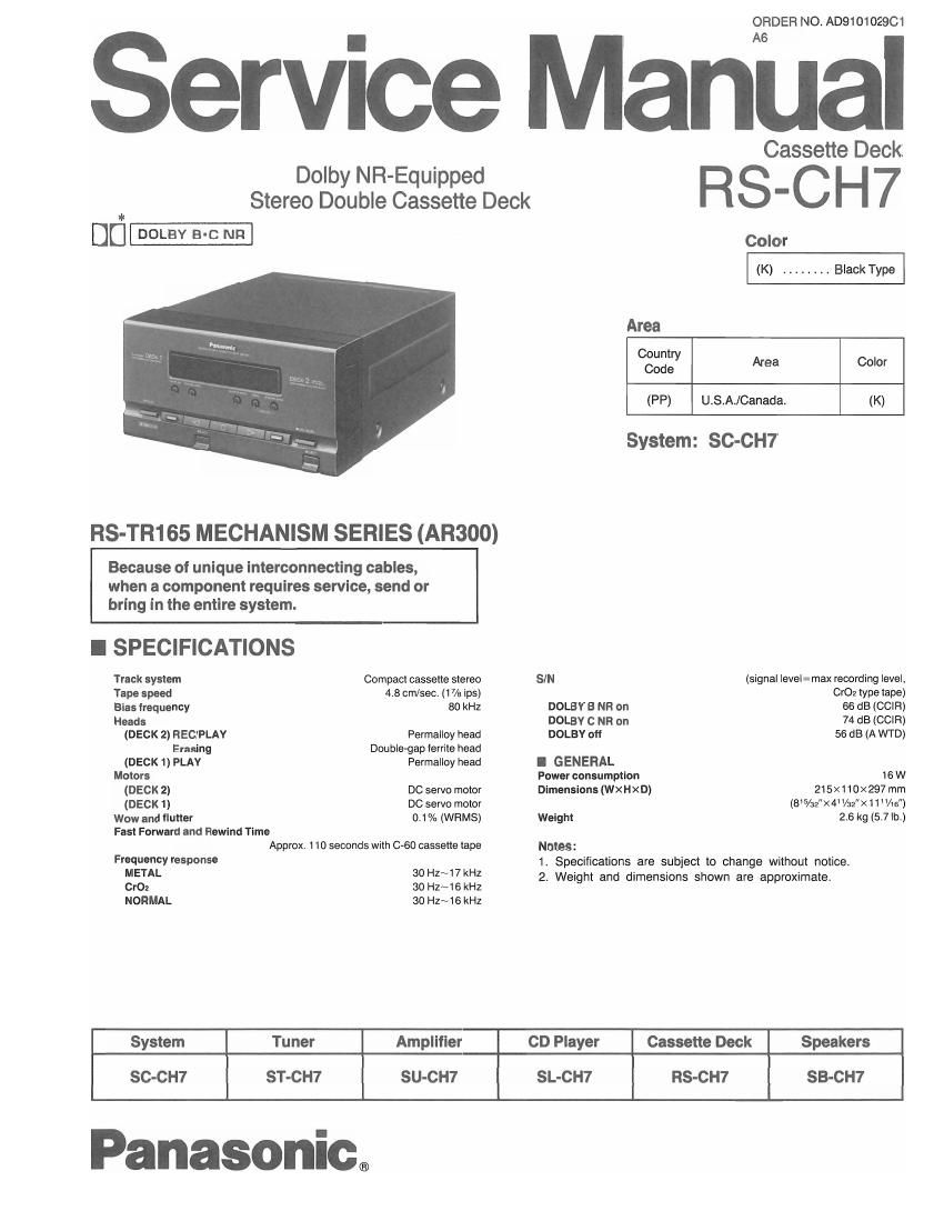
Technics RSCH 7 Service Manual

This is the 26 pages manual for Technics RSCH 7 Service Manual.
Read or download the pdf for free. If you want to contribute, please mail your pdfs to info@audioservicemanuals.com.

Page: 1 / 26
left right
Technics RSCH 7 Service Manual

Extracted text from Technics RSCH 7 Service Manual (Ocr-read)


Page 1

ORDEFI NO. AD910102QC1

Service Manual

R863???"

Dolby NR-Equipped
Stereo Double Cassette Deck

Uti-

Color
(K) ........ Black Type
Area
Country
Code Area Color
(PP) USA/Canada. (K)

System: SC-CH7

RS-TR165 MECHANISM SERIES (AR300)

Because of unique interconnecting cables,
when a component requires service, send or
bring in the entire system.

I SPECIFICATIONS
Track system Compact cassette stereo SIN (signal |eve|=max recording level,
Tape speed 4.8 cm/sec. (17/a ips) Cr02 type tape)
Bias trequency 80 kHz DOLBV B NR on 66 dB (CCIR)
Heads DOLBV O NH on 74 dB (CCIR)
(DECK 2) REC/PLAY Permalloy head DOLBY D 56 dB (A WTD)
Erasing Double-gap territe head
(DECK 1) PLAY Permallcy head I GENERAL
Motors Power consumption 16 W
(DECK 2) DC servo motor Dimensions (WXHXD) 215xt1o><297 mm
(DECK 1) DC servo motor (85/32><4 l/az">< 1 1 "/1 5)
Wow and Ilutter 0.1% (WRMS) Weight 2.6 kg (5.7 lb.)

Fast Forward and Rewind Time

Approx. 1 10 seconds with 0-60 cassette tape

Frequency response

Notes:
1. Specifications are subiect to change without notice.

METAL 3° H147 kHz 2. Weight and dimensions shown are approximate.

CrOz 30 Hz~16 kHz

NORMAL 30 Hz~16 kHz
System Tuner Amplifier CD Player Cassette Deck Speakers
SC-CH7 ST-CH7 SU-CH7 SL-CH7 RS-CH? SB-CH7

Panasonic.

Page 2

RS-CH7

I CONTENTS

Page Page
SAFETY PRECAUTION .................................. 2 PRINTED CIRCUIT BOARDS AND
LOCATION OF CONTROLS .. . . .. 3 WIRING CONNECTION DIAGRAM ...... 20~22
DISASSEMBLY INSTRUCTIONS .......................... 4~7 FUNCTION CF to TERMINALS ............ . . 23, 24
DESCRIPTION OF FL PANEL ............................ REPLACEMENT PARTS LIST .............. 25~37
MEASUREMENTS AND ADJUSTMENTS MECHANISM PARTS LOCATION (DECK t) 29, 30
BLOCK DIAGRAM .................... . . (DECK 2) 33, 34
SCHEMATIC DIAGRAM .............................. 14~19 CABINET PARTS LOCATION .......... . 35, 36

I SAFETY PRECAUTION

Betore servicing, unplug the power cord to prevent an electric shock.

When replacing parts. use only manufacturer's recommended components for safety.

Check the condition ot the power cord. Replace it wear or damage is evident.

After servicing. be sure to restore the lead dress. insulation barries, insulation papers, shields. etc.

Before returning the serviced equipment to the customer, be sure to make the following insulation resistance test to prevent the
customer from being exposed to a shock hazard.

OINSULATION RESISTANCE TEST

1. Unplug the power cord and short the two prongs of the plug with a jumper wire.

2. Turn on the power switch.

3. Measure the resistance value with ohmmeter between the jumpered AC plug and each exposed metal cabinet part, such as
screwheads antenna, control shafts, handle brackets, etc. Equipment with antenna terminals should read between 3 MO and

5.2 M0 to all exposed parts. (Fig, A) Equipment without antenna terminals should read approximately intinity to all exposed
parts. (Fig. B)

9939!?

Note: Some exposed parts may be isolated lrom the chassis by design. These will read intinity.


Antenna
terminal \J I

Exposed / Exposed /"°
metal metal
part part
3 Ohmmeter Ohmmeter
(Fig A) (Fig. 13)
Resistance=3 MQ-5.2 M0 Resistance2Approx. (>0

4. It the measurement is outside the specitied limits. there is a possibility of a shock hazard. The equipment should be repaired and
rechecked before it is returned to the customer.

NOTES:

Refer to the service manual for Model No. SU-CH7, Order No. AD9101027C1 for information on ACCESSORIES,
INSTALLATION OF THE SYSTEM, CONNECTIONS and PACKAGING.

Page 23

RS-CH7 RS-CH7

I MECHANISM PARTS LOCATION ODECKZ

1 I 2 I 3 l 4 l 5 l 6 I 7 | e | 9
it 26! 2 6 9

A \
_.
B
C
1
D
E
-.

Note:

when changing mechanism parts, apply the

specified grease to areas marked XX as

shown in the drawing.
F R f

e .
No. Part Name Pan No.
o FLOILAK-152 SZZOL18 \]
243 216

_ C FLOIL 947P RZZOL 02 0

-33- -34_