Technics RSCH 610 Schematics

This is the 10 pages manual for Technics RSCH 610 Schematics.
Read or download the pdf for free. If you want to contribute, please mail your pdfs to info@audioservicemanuals.com.

Page: 1 / 10
left right
Technics RSCH 610 Schematics

Extracted text from Technics RSCH 610 Schematics (Ocr-read)


Page 1

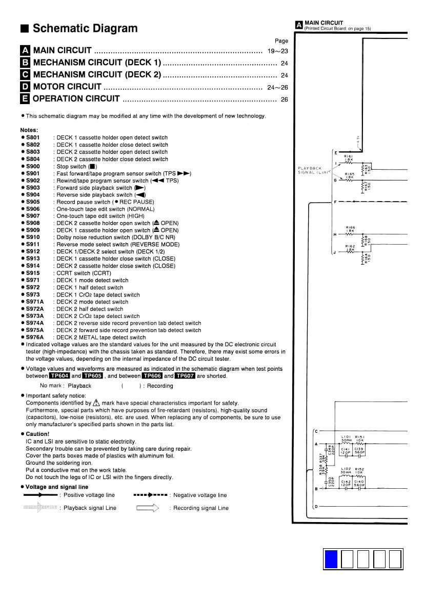
I Schematic Diagram

Page
MAIN CIRCUIT ................................ .............................. 19%
E] MECHANISM CIRCUIT (DECK 1) ................................................. 24
I MECHANISM CIRCUIT (DECK 2).. .. . 24
E] MOTOR CIRCUIT .................................................................... 24~26
E OPERATION CIRCUIT .................................................................. 26
I This schematic diagram may be modIlied at any tIme with the development ol new technology.
Notes:
I 5801 : DECK 1 cassette holder open detect switch
I 5802 : DECK 1 cassette holder close detect switch
I 5803 : DECK 2 cassette holder open detect switch
I 5804 : DECK 2 cassette holder close detect switch
I 8900 : Stop switch (I)
I 5901 : Fast forward/tape program sensor switch (TPS »)
I 5902 : Rewind/tape program sensor switch (« TPS)
I 8903 : Forward side playback switch P)
I 8904 : Reverse side playback switch (<)
I 5905 : Record pause switch (I REC PAUSE)
I 5906 ' One-touch tape edit switch (NORMAL)
I 5907 '. One-touch tape edit switch (HIGH)
I 5905 DECK 2 cassette holder open switch (5 OPEN)
I 5909 : DECK 1 cassette holder open switch (2 OPEN)
I 5910 : Dolby noise reduction switch (DOLBY B/C NR)
I 5911 : Reverse mode select switch (REVERSE MODE)
I 5912 : DECK 1/DECK 2 select switch (DECK 1/2)
I $913 : DECK 1 cassette holder close switch (CLOSE)
I 5914 : DECK 2 cassette holder close switch (CLOSE)
I 5915 : CCRT switch (CCRT)
I 5971 : DECK 1 mode detect switch
I 5972 : DECK 1 half detect switch
I 5973 : DECK 1 Cr02 tape detect switch
I 5971A : DECK 2 mode detect switch
I 5972A : DECK 2 half detect switch
I S973A : DECK 2 Cr02 tape detect sw1tch
I $974A : DECK 2 reverse side record prevention tab detect switch
I $975A : DECK 2 forward side record prevention tab detect switch
I $976A : DECK 2 METAL tape detect switch

I Indicated voltage values are the standard values for the unit measured by the DC electronic circuit
tester (high»impedance) with the chassis taken as standard. Therefore. there may exist some errors in
the voltage values. depending on the internal impedance of the DC circuit tester.

I Voltage values and waveforms are measured as indicated in the schematic diagram when test points

between TP604 and TPGOS .and between TF606 and TP607 are shoned.

No mark: Playback ( ) : Recording

I Important safety notice:
Components identified byA mark have speCIal characteristlcs Important for safety.
Furthermore. special parts which have purposes of firevretardant (resistors). high-quality sound
(capacitors). low-noise (resistors). etc. are used. When replacing any of components. be sure to use
only manufacturer's specified pans shown in the parts list.

0 caution!
IC and LSI are sensitive to static electricity.
Secondary trouble can be prevented by taking care during repair.
Cover the parts boxes made of plastics with aluminum foil.
Ground the soldering iron.
Put a conductive mat on the work table.
Do not touch the legs of IC or LSI with the fingers directly.

0 Voltage and signal line
-§- : Positive voltage line

"...-...;

E)

Negative voltage line

: Playback signal Line . Recording signal Line

MAIN CIRCUIT
(Printed Circull Board: on page 15)

I
PLAVEACK < / @g
SIGNALILCM \ a. we
6

Rise
Iax
H u
we
R162 R-
9k
J V
o
2.»
r
c
Llol W15)
mm 10K
1mm
we Cldl use
F 3: mop 56o?
x -l
20»
Km
"3" LIOZ R152
;: somn on
°3
2... Cl C140
UN )2 5605
ai-LHDE
o