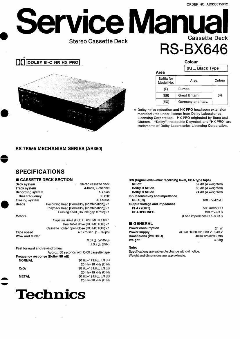
Technics RSBX 646 Service Manual

This is the 32 pages manual for Technics RSBX 646 Service Manual.
Read or download the pdf for free. If you want to contribute, please mail your pdfs to info@audioservicemanuals.com.

Page: 1 / 32
left right
Technics RSBX 646 Service Manual

Extracted text from Technics RSBX 646 Service Manual (Ocr-read)


Page 1

ORDER NO. A0930515902

Service Manual

Stereo Cassette Deck Cassette Deck

06- .

RS-TRS55 MECHANISM SERIES (AR350)

SPECIFICATIONS

I CASSETTE DECK SECTION

Deck system Stereo cassette deck

Track system 4-track, 2-channel

Recording system AC bias
Bias frequency 80 kHz

Erasing system AC erase

Heads Recording head [Permalloy (combinationflxl

Playback head [Permalloy (combinationflxl
Erasing head (Double-gap ferrite)x1

Motors

Capstan drive (DC SERVO MOTOR)><1
Fleel table drive (DC MOTOR)><1
Cassette holder open/close (DC MOTOR))<1
Tape speed 4.8 cm/sec. (1 -7/a ips)

Wow and flutter
0.07% (WRMS)
t0.2% (DIN)

Fast forward and rewind times
Approx, 50 seconds with 0-60 cassette tape
Frequency response (Dolby NR off)

NORMAL 30 Hz-17 kHz, :3 dB
20 Hz-18 kHz (DIN)
OK); 30 Hz-1 8 kHz, i3 dB
20 Hz-19 kHz (DIN)
METAL 30 Hz-19 kHz, i3 dB

20 HZ-ZO kHz (DIN)

Technics

RS-BX646

Colour
Area .
5:3: Log. Area Colour
(E) Europe.
(EB) Great Britain. (K)
(EG) Germany and Italy.

>t< Dolby noise reduction and HX PRO headroom extension
manuiactured under license from Dolby Laboratories
Licensing Corporation. HX PRO originated by Bang and

Olufsen. Dolby, thedoubIe-D symbol, and HX PRO" are

trademarks of Dolby Laboratories Licensing Corporation.

S/N (Signal level=max recording level, Cro; type tape)

NR off 57 dB (A weighted)

Dolby B NR on 66 dB (A weighted)

Dolby C NR on 74 dB (A weighted)
Input sensitivity and impedance

REC (IN) 100 mV/47 kQ
Output voltage and Impedance

PLAY (OUT) 500 mV/SOOQ

HEADPHONES 190 mV/(BQ)

(Load impedance 80-6000)

I GENERAL
Power consumption 21 w
Power supply AC 50 Hz/60 Hz, 230 V-240 V
Dimensions (WxHxD) 430x125x293 mm
Weight 4.6 kg
Note:

Specifications are subject to change without notice.
Weight and dimensions are approximate.

Page 2

RS-BX64i'

I CONTENTS

ACCESSORIES ..
CONNECTIONS.
CAUTION FOR AC MAINS LEAD....
FRONT PANEL CONTROLS AND FUNCTION
PLAYBACK (Basic play) ........
DISASSEMBLY INSTRUCTIONS
ADJUSTMENT PROCEDURE ...............
MEASUREMENTS AND ADJUSTMENT
TROUBLESHOOTING GUIDE
TERMINAL FUNCTION OF lC..

BLOCK DIAGRAM .........................................................

I ACCESSORIES

AC power supply cord ................................. 1pc.
(VJA0733) ............ (EB) (RJA0019-2K) ...... (E, E6)

Page
SCHEMATIC DIAGRAM ........................................................ 31~38
TERMINAL GUIDE 0F ICS TRANSISTORS AND DIODES ...... 31
PRINTED CIRCUIT BOARDS....... 39~42
WIRING CONNECTION DIAGRAM.
INTERNAL CONNECTION OF FL
CABINET PARTS LOCATION ..
REPLACEMENT PARTS LIST.. ...... 41, 4a, 51, 52
PACKAGING 48
MECHANISM PARTS LOCATION 49, 50
RESISTORS AND CAPACITORS 53, 54


Stereo connection cables ............................. 2pcs.
(SJP2276)

I CONNECTIONS

Make connections in the numbered sequence by using the included
cables.

Rear panel
of this unit

REEIIM) Puriotm

@ @
IE 0 0
(white) (red)
'
(red) (white)
(red) (white) [2] Household
ACoutlet

Amplifier or receiver

(white) (red)
(not included)

gee

REC PLAY
(our) (lN)

The above illustration shows an example of connections made
when this unit is combined with a Technics hi-ti component system.
and shows only the connections to be made to and from this unit in
that combination.

m Connect the stereo connection cables.

FOR UNITED KINGDOM ONLY
BE SURE TO READ THE CAUTION FOR AC
POWER SUPPLY CORD 0N PAGE 3 BE-
FORE PROCEEDING TO THE STEP 2.

[2] Connect the AC power supply cord after you
have connected all other cables and cords.
The configuration of the AC outlet and AC power supply cord
differs according to area

Insertion ot Connector

Even when the connector is per-
iectly inserted, depending on the
type of inlet used, the front part of
the connector may jut out as
shown in the drawing.

However there is no problem
using the unit

Connector

Approx. 6 mm
Appliance inlet

Note:
Avoid letting the cables touch each other as much as possible,
otherwise noise will be generated.

Placements hints

It this unit is placed near a receiver or a tuner, a "hum" noise may
be heard during tape playback, recording, or AM reception of the
receiver or the tuner.

If this occurs, leave as much space as possible between the units.
or place them where is the least amount of hum".

H