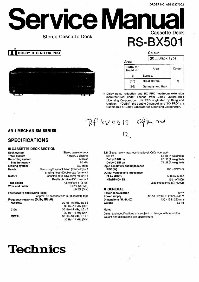
Technics RSBX 501 Service Manual

This is the 58 pages manual for Technics RSBX 501 Service Manual.
Read or download the pdf for free. If you want to contribute, please mail your pdfs to info@audioservicemanuals.com.

Page: 1 / 58
left right
Technics RSBX 501 Service Manual

Extracted text from Technics RSBX 501 Service Manual (Ocr-read)


Page 1

ORDER NO. AD9403072C2

Service Manual

Stereo Cassette Deck

DU-

Cassette Deck

RS-BX501

Colour
(K) Black Type

Area
Suffix for
Model No. Area Colour
(E) Europe.
(EB) Great Britain. (K)
(EG) Germany and Italy.

>I< Dolby noise reduction and HX PFIO headroom extension
manufactured under license irom Dolby Laboratories
Licensing Corporation. HX PFIO originated by Bang and
Oluisen. Dolby", the double-D symbol, and "HX PRO" are
trademarks of Dolby Laboratories Licensing Corporation.

)2? Itvm I3 ((4% we

AR-1 MECHANISM SERIES

SPECIFICATIONS

I CASSETTE DECK SECTION

Deck system
Track system

Stereo cassette deck
4-track, 2-channeI

Recording system AC bias
Bias frequency 80 kHz
Erasing system AC erase
Heads Recording/Playback head (Permalloy)x1
Erasing head (Double-gap ferrite)x1

Motors Capstan drive (DC servo motor)><1
Reel table drive (DC motor)x1

Tape speed 4.8 cm/sec. (17/8 ips)

Wow and flutter 0.07% (WRMS)
i0.2% (DIN)

Fast toward and rewind times
Approx. 50 seconds with 0-60 cassette tape

Frequency response (Dolby NR off)

NORMAL 30 Hz-15 kHz, :3 (.15

so Hz-16 kHz (DIN)
OrO: so Hz-15 kHz, 13 dB
so Hz-iG kH_z (DIN)
METAL so Hz-16 kHz, :3 dB

so Hz-l7 kHz (DIN)

Technics

11,

SIN (Signal level=max recordIng level, CIO: type tape)

NR off 56 dB (A weighted)

Dolby B NR on 66 dB (A weighted)

Dolby O NH on 74 (18 (A weighted)
Input sensitivity and impedance

REC (IN) 100 mV/47 kn
Output voltage and Impedance

PLAY (OUT) 500 mV/SOOQ

HEADPHONES 190 mV/(BQ)

(Load impedance 89-6000)

I GENERAL
Power consumption 19 W
Power supply AC 50 Hz/eo Hz. 230 V-240 V
Dimensions (WXHXD) 430x 125x293 mm
Weight 8.3 kg
Note:

Disign and specifications are subject to change without notice.
Weight and dlmenslons are approximate.

Page 2

RS-BX501

I CONTENTS

CAUTION FOR AC MAINS LEAD.
FRONT PANEL CONTROLS..
ACCESSORIES ......
CONNECTIONS.
PLAYBACK .........
T0 FAST-FORWARD OR REWIND THE TAPE.
ABOUT THE ATC FUNCTION
SELF-DIAGNOSTIC ................
DISASSEMBLY INSTRUCTIONS
WRITING TO EEPROM..~ .............
MEASUREMENTS AND ADJUSTMENTS
TROUBLESHOOTING GUIDE....

ICAUTION FOR AC MAINS LEAD
For (EB) area only


For your safety, please read the following text care-
fully.

This appliance is supplied with a moulded three pin
mains plug for your safety and convenience.

A 5-ampere fuse is fitted in this plug.

Should the fuse need to be replaced please ensure
that the replacement fuse has a rating of 5-ampere and
that it is approved by ASTA or BSI to 351362.

Check for the ASTA mark @ or the BSl mark @ on
the body of the fuse.

it the plug contains a removable fuse cover you must
ensure that it is refitted when the fuse is replaced.

if you lose the fuse cover the plug must not be used
until a replacement cover is obtained.

A replacement fuse cover can be purchased from your
local dealer.

CAUTION!

IF THE FITTED MOULDED PLUG IS UNSUIT-
ABLE FOR THE SOCKET OUTLET IN YOUR
HOME THEN THE FUSE SHOULD BE RE-
MOVED AND THE PLUG CUT OFF AND DIS-
POSED OF SAFELY.

THERE IS A DANGER OF SEVERE ELECTRI-
CAL SHOCK IF THE CUT OFF PLUG IS IN-
SERTED INTO ANY 13-AMPERE SOCKET.

If a new plug is to be titted please observe the wiring
code as shown below.
If in any doubt please consult a qualified electrician.

IMPORTANT
The wires in this mains lead are coloured in accor-
dance with the following code:

Blue: Neutral

Brown: Live
As the colours of the wires in the mains lead of this
appliance may not correspond with the coloured mark-
ings identifying the terminals in your plug, proceed as
follows:
The wire which is coloured BLUE must be connected
to the terminal in the plug which is marked with the
letter N or coloured BLACK.


BLOCK DIAGRAM ..........
SCHEMATIC DIAGRAM
PRINTED CIRCUIT BOARDS.

REPLACEMENT OF THE FOOT 43
WIRING CONNECTION DIAGRAM . M
TERMINAL FUNCTION OF IC... . 45~47
REPLACEMENT PARTS LIST .. 48, 53~55, 51
PACKAGING ................................ 48
CABINET PARTS LOCATION 49, 50
MECHANISM PARTS LOCATION.. 51, 52
RESISTORS AND CAPACITORS .. 56, 57

The wire which is coloured BROWN must be con-
nected to the terminal in the plug which is marked with
the letter L or coloured RED.

Under no circumstances should either of these wires
be connected to the earth terminal of the three pin
plug. marked with the letter E or the Earth Symbol Jim

Before use
Remove the connector cover as follows.

Connector
cover

How to replace the fuse
1. Remove the fuse cover with a screwdriver.

Fuse
(5 ampere)

Page 14

RS-BX501

6. Replacement for the mechanism unlt

Follow the disassembly procedure descrlbed
in item 1 on page 9.

Step 2 Remove the connectors.

CN2B

CP1

CNSB

Push the drlve lever and open the cassette
holder assy.

Drive lever

@ Remove the 4 screws and connector,

Mechanism unit

CN502 a f

Remove the 4 screws.

Front panel assy [RFKGSBX501EK]

Lift the cassette lid in the direction of arrow®,
and remove it in the direction of arrow®.

Cassette lid [RYFOZSB- K]

@mm 0~6
[XTBSS+8JH1] (Black)

.)|mm 6 ~ 9
[XTBSH ZJFZ] (Black)

__14__

Page 47

RS-BX501

Pln IIO .
Na. Mark Dlvlslon Function Check polnt X Dlserlptlon
53 - - Not used w -
54 - - Not used - -
55 - - Not used - -
56 - - Not used - -
Connector
57 VDD - Mlcrooomputer termlnal CN501 ® pin +5v, Backup
_ FL meter pull down voltage Connector _
58 'VP lnput termlnel CN501 0]) pln 20"
Connector
59 AVss -- GND termlnal (AID) CN501 (3, pln 0V
Relerence power supply Connector
6° VREF ' (+5vl (AID) CN501 (9) pln +5V
Changes within the O <->
3V range each tlme the
Real pulse det. lnput (take up Connector av
61 RPT I take up reel ls through
elde) CN502 6) pln o approxlmately 30
degrees.
No tape load: Approx. 4.1 V
Deck 2 Mechanlsm SWICh Connector Normal tape wlth tab: Apprxo. CV
62 AD01 l (FlNH, CrOz, Metal, 0 h b'
OPENICLOSE) Input CN502 ® pln hrome tape wlt ta . 1.1V
Metal tape wlth tab: Approx. 1.7V
Changes withln the 0 «
3V range each tlme the
av
63 RPS :lzealfulse det. Input (supply gaggzcgr in 0 ML take up real is through
p approxlmately 30
degrees.
64 AD02 I Deck 2 Mechanism swltch Connector No tape load: Approx. 4.1 V
(MODE, RINH, HALF) input CN502 (D pln Normal tape wlth tab: Approx. 2.3V

_47_