Technics RSB 765 Service Manual

This is the 38 pages manual for Technics RSB 765 Service Manual.
Read or download the pdf for free. If you want to contribute, please mail your pdfs to info@audioservicemanuals.com.

Page: 1 / 38
left right
Technics RSB 765 Service Manual

Extracted text from Technics RSB 765 Service Manual (Ocr-read)


Page 1

OR DER N0. ADSOMOSSAZ

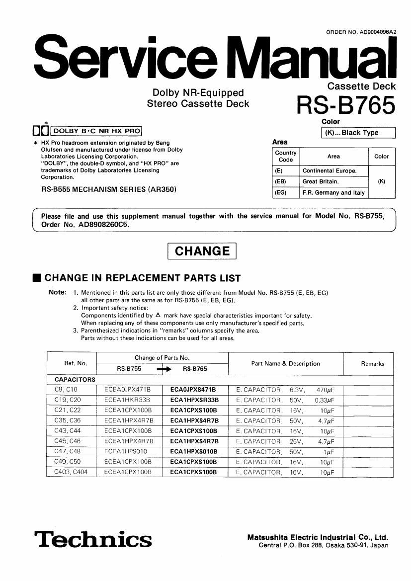
ervice Manual

Dolby N R-Equippe d Cassette Deck

Stereo Cassette Deck R S- B 76 5

* Color

DD DOLBY B-c NR HX PRO (K)_,_B|ack Type

=l< HX Pro headroom extension originated by Bang Area
Oqusen and manufactured under license from Dolby Country
Laboratories Licensing Corporation. Code Area Color
"DOLBY", the double-D symbol. and HX PRO" are
trademarks of Dolby Laboratories Licensing (E) Continental Europe.
c°'°°ra"°"' (EB) Great Britain. (K)
RS-B555 MECHANISM SERIES (AR350) (EG) ER, Germany and Italy

Please file and use this supplement manual together with the service manual for Model No. RS-B755,
Order No. ADSQOBZGOCS.

CHANGE

I CHANGE IN REPLACEMENT PARTS LIST

Note: 1. Mentioned in this parts list are only those different from Model No. RS-B755 (E, EB, EG)
all other parts are the same as for RS-B755 (E, EB, E6).
2. Important safety notice:
Components identified by A mark have special characteristics important for safety.
When replacing any of these components use only manufacturers specified parts.
3. Parenthesized indications in "remarks columns specify the area.
Parts without these indications can be used for all areas.

Change of Parts No.
Ref. No. Part Name & Description Remarks
RS-B755 .l» RS

CAPACITORS

C9, C10 ECEAOJPX47IB ECAOJPX5471B E, CAPACITOR, 6.3V, 470uF
C19,C20 ECEAIHKR33B ECA1HPXSR333 E. CAPACITOR, 50V, 0.33MF
C21, C22 ECEAICPXIOOB ECA1CPXS1OOB E. CAPACITOR, 16V, IOuF
C35, C36 ECEAI HPX4R7B ECA1HPXSdR7B E. CAPACITOR] 50V, 4.7uF
C43, C44 ECEAICPXIOOB ECA1CPXS1OOB E, CAPACITOR, 16V, IOuF
C45, C46 ECEAIHPX4R7B ECA1HPXS4R7B E. CAPACITOR, 25V, 4.7m:
C47, C48 ECEAIHPSOIO ECA1HFXSO1OB E, CAPACITOR, 50V, IuF
C49, C50 ECEAICPXIOOB ECA1CPXS1OOB E. CAPACITOR, 16V, lOuF
C403, C404 ECEAICPXIOOB ECA1CPXS1OOB E. CAPACITOR, 76V] IOpF

' I 'echnics Matsushlta Electric Industrial Co., Ltd.
Central PO. Box 288, Osaka 530-91. Japan

Page 14

RS-B755

Drive Gear

1. Release the 2 claws.
2. Remove the drive gear in the direction of the arrow

not. No. - Removal of the intermediate gear leaf
Removal of the drive ear I
15 9 R°'16N° switch lever-A, leaf switch lever-B. and
Procedure Claws leaf switch lever-c
#15 P'°°°d"° I Removal of the intermediate gear
"15 1. Release the 2 claws.

0.
Ref. No. Installation of the Drive Gear and the
17 Drive Sector Lever
Procedure I Installation of the Drive Gear
17 1. Push the leaf switch lever A in the

direction of the arrow.
2. Place the drive gear as shown below
and then Install it in the loading base.


Leaf Switch Lever-A

Drive Gear

2. Remove the intermediate gear in the
direction of the arrow 6.

Intermediate Gear
I Removal of the leaf switch lever-A
0Release the 1 claw.
I Removal of the leaf switch lever-B
Release the 1 claw.

I Removal of the leaf switch lever-C
-Release the 1 claw.

Claw

Leaf Switch Lever»c

Claw

Leaf Switch Leve r-B


4
2. Install the loading angle in the loading base and
then secure it with the 1 screw 0.
3. Push the leaf switch lever C in the direction of the
arrow.
4. Secure the drive sector lever with 1 screw 0.
I Installation of the Drive Sector Lever 5- Engage the Open Spring in the claw 0f the loading
1. Temporarily install the open spring in the drive base.
sector lever.
seem m

Drive Sector
Lever

712,