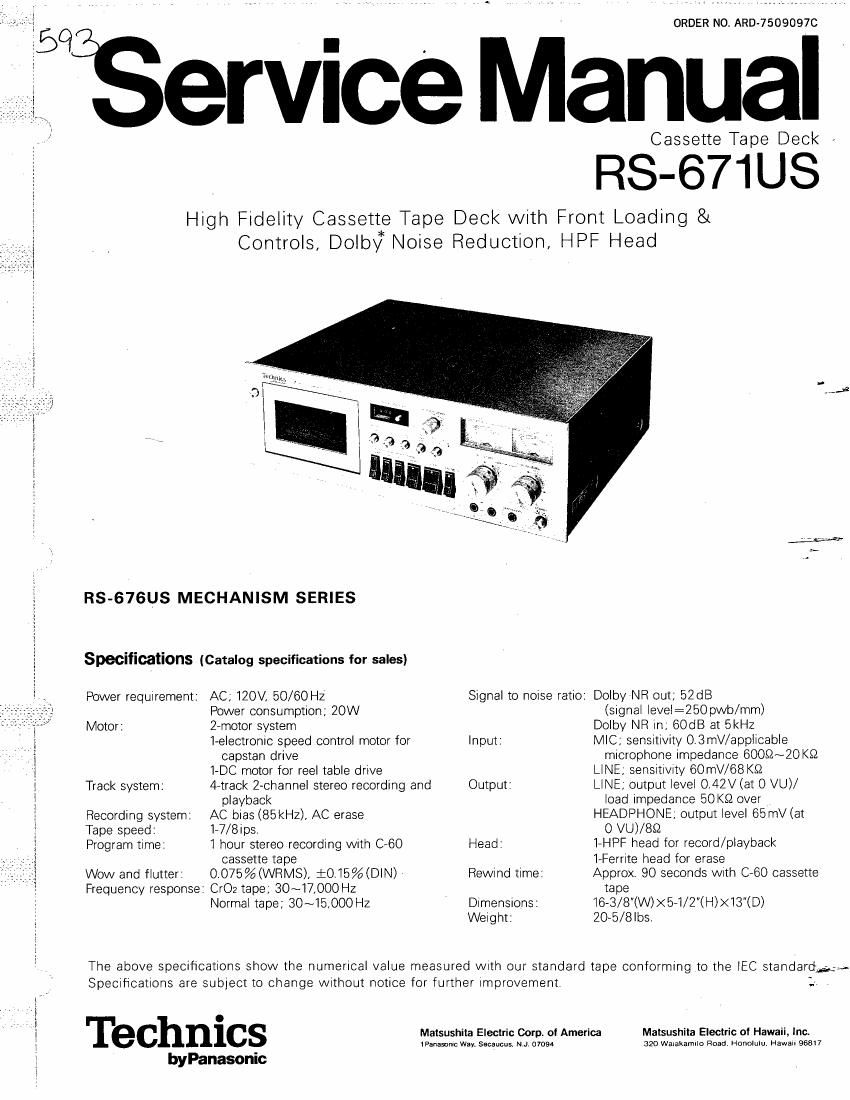
Technics RS 671 US Service Manual

This is the 40 pages manual for Technics RS 671 US Service Manual.
Read or download the pdf for free. If you want to contribute, please mail your pdfs to info@audioservicemanuals.com.

Page: 1 / 40
left right
Technics RS 671 US Service Manual

Extracted text from Technics RS 671 US Service Manual (Ocr-read)


Page 1

ORDER NO. ARD- 75090970

Service Manual

Cassette Tape Deck

RS-67IUS

High Fidelity Cassette Tape Deck with Front Loading 8t
Controls, Dolbyk Noise Reduction, HPF Head

.AJ

RS-676US MECHANISM SERIES

Specifications (Catalog specifications for sales)

Power requirement: AC; 120V. 50/60 HZ Signal to noise ratio: Dolby'NR out; 52dB
Power consumption; 20W (signal level:260pvvb/mm)
» Motor: 2-motor system Dolby NR In, 60:18 at SkHz
i 1~e|ectronic speed control motor for Input: MIC, sensrtivity 0.3mV/applicable
i capstan drive microphone impedance 6OOSZ~ZO KQ
l 1-DC motor for reel table drive LINE; sensrtivrty 60mV/68 K32
I Track system: 4-track 2-channel stereo recording and Output: LINE, output level O.42V(at 0 VU)/
3 playback load impedance 50 K9 over
§ Recording system: AC bias (85kHz), AC erase HEADPHONE, output level 65mV (at
Tape speed: 1-7/8Ips, O VU)/8£2
Program time: 1 hour stereo recording with 060 Head: l-HPF head for record/playback
cassette tape 1»Ferrite head for erase
Wow and flutter: 0.075%(WRMS), iO.l§%(DIN) Rewind time: Approx 90 seconds With C- 60 cassette
Frequency response: Cr02 tape; 30~17,000HZ tap e
; Normal tape; 30~15,000 HZ Dimensions: 16 3/8"(W)><5- 1/2(H)> Weight: 20- 5/8Ibs.

The above specifications show the numerical value measured With our standard tape conforming to the lEC standards: ,
Specifications are subject to change without notice for further improvement _:

1 > J
T C C

i e hni S Matsushita Electric Corp. of America Matsushita Electric of Hawaii. Ina
tPanasonrc Way. Sscaucus, N.JV 07094 320 Waiakamrlo Head Honolulu. Hawaii 96517

j byPanasonic

Page 2

LOCATION OF CONTROLS AND

COMPONENTS
(D

G) Ejection button

62) Cassette cover

@ Memory-rewind switch
© Bias selector

6) Tape counter and reset button
Equalization selector

("D Output level control
Peal/(signal check button
© VU meters

Microphone level control
@ Line input level control
® Power switch

® Headphones jack

Fig. '1

@ Microphone jacks
@ Pause button
Stop button

® Playback button

. Fast forward button

® Rewind button

® Record button

@ Recording indication lamp
® Dolby noise-reduction switch
® Ground terminal

@ Line output jacks

@ Line input jacks

1= Dolby is the trade mark of Dolby Laboratories lnc.

Page 5

i
i

ADJUSTMENTS

Before measuring and adjusting "Overall Frequency Response", "Overall Distortion" and Overall S/N Ratio", confirm
that the characteristics of 5 items below are within standard which have much relation to or influence on electrical
performances above.

1. Head Azimuth Adjustment 2. Bias current 3, Playback Gain 4. Overall Gain

5. Playback Frequency Response

I. TEST INSTRUMENTS

1. Prepare test instruments which are equivalent in accuracy to those shown below.

2. The test instruments should be inspected and corrected by specialists once every 6 months, because a long
period of use without maintenance may increase errors in indication.

3. Warm up the test instruments for 30 minutes and the set to be measured for 10 minutes before taking the
measurements. If not, there may arise an error or difference between the initial value and the stablized ,
value measured after "aging". ""4

4_ Specifications of Test Instruments

(1) Audio Frequency Oscillator

a. Oscillation Frequency: 5 Hz~500 kHz (5 ranges)
b. Frequency Tolerance: i (3% +1 Hz)
0. Sine Wave
* Output Voltage: 5 Vrmsi 10% (without load)
(at 25°C) 2.5 VrmsilOO/o (with 600.0 load) .Lvm

* Output Frequency Response:
Withini-O.2 dB, 20 Hz~20 kHz
WithiniOf) dB, 5 Hz~500 kHz

* Distortion Factor: Not more than 0.05%, 200 Hz~20 kHz
' Not more than 0.5%. 5 Hz~500 kHz

* Output Impedance: 6000 unbalanced. Withini15%

* Output Attenuator: O, 20 dB. Error: WithiniOZ dB

d. Temperature In Use of Set: Temperature=0~40°CI Humidity=90% or less

(2) Automatic-stop Distortion Meter (with Vacuum Tube Voltmeter)

A. Distortion Factor Measurement C. Output Terminal
a. Frequency (Fundamental wave): a. Frequency Response: 10 Hz~1OO kHz: 1 dB
400 Hz, 1 kHZilOJ/fi 100 kHz~1 MHZi3 dB
b. Measurement: O.1%~100% (6 range) b. Output Voltage:
c. Input: 50 mv~50 V 1 Vrmsi10% (1 kHz sine wave)

d. Fundamental Wave Attenuation:
60 dB or more
B. Level Measurements
a. Measurement:
1 mV (760 dB)~30 V (30 dB) 9 range
b. Frequency Response (1 kHz basis):
20 Hz~100 kHziOB dB

0

. Input Impedance:

lMQi-10%, Less than 50 pF
d. Error in Indicated Value:
Within i3% at 1 kHz