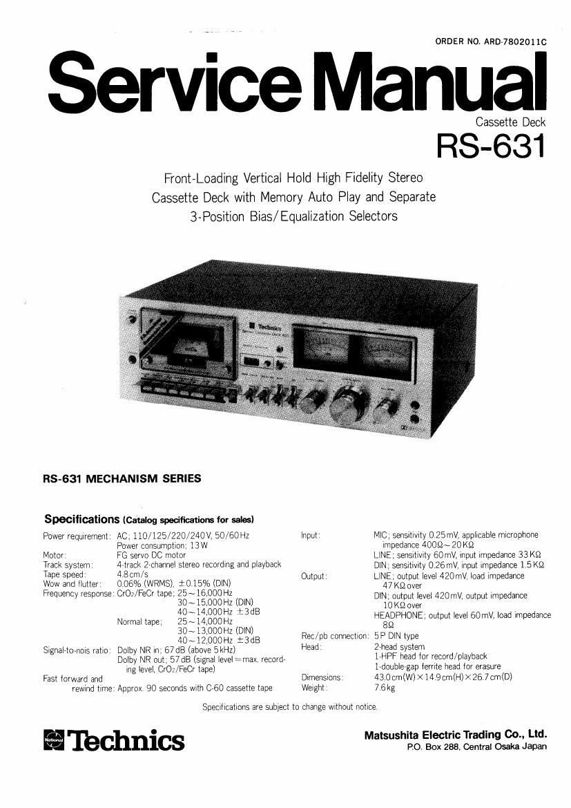
Technics RS 631 Service Manual

This is the 16 pages manual for Technics RS 631 Service Manual.
Read or download the pdf for free. If you want to contribute, please mail your pdfs to info@audioservicemanuals.com.

Page: 1 / 16
left right
Technics RS 631 Service Manual

Extracted text from Technics RS 631 Service Manual (Ocr-read)


Page 1

ORDER NO. ARD-78020110

Service Manual

Cassette Deck

RS-631

Front-Loading Vertical Hold High Fidelity Stereo
Cassette Deck with Memory Auto Play and Separate
3-Position Bias/ Equalization Selectors

RS-631 MECHANISM SERIES

Specifications (Catalog specifications for sales)

Power requirement

Motor,

Track system.

Tape speed:

Wow and llutter
Frequency response:

Signaleto-nOis ratio

Fast forward and
rewind time:

AC,110/125/220/240V,50/60Hz
Power consumption; 13W

PG servo DC motor

4-track Zechannel stereo recording and playback
4.8cm/s

0.06% (WRMS), i0.15% (DlN)
CrO2/FeCr tape; 25~16,000Hz
3O~15,OOOHZ (DIN)
40~14,OOOH2 i3dB
25~14.OOOH2
30~13.000HZ (DlN)
40~12,000Hz i3dB
Dolby NR in; 67 dB (above 5kHz)

Normal tape;

Dolby NR out; 57 dB (signal level :max record-

ing level, CrOz/FeCr tape)

Approx. 90 seconds with 060 cassette tape

Input

Output :

Rec/pp connection
Head:

Dimensions:
Weight:

MIC; sensitivity 0.25mV, applicable microphone
impedance 400§2~ 20 K9

LINE; sensitivity 60 mV, input impedance 33 K9

DlN; sensitivity 0.26 mV, input impedance 1 5K9

LINE; output level 420mv, load impedance
47 KS2 over

DIN. output level 420 mV, output impedance
10 K9 over

HEADPHONE ; output level 60 mV, load Impedance
89

5 P DlN type

27head system

l-HPF head for record/ playback

l-doublegap ferrite head for erasure

43.0 cm (W) X 149 cm(H) X 26.7 cm (D)

7 6 kg

Specifications are subject lo change without notice,

Matsushita Electric Trading 00., Ltd.
PO. Box 288, Central Osaka Japan

I'Ibchnics

Page 2

2 C3)

6) Power switch

(2) Headphones jack

® Cassette compartment door
® Tape counter and reset button
(5) Memory indication lamp

© Memory sWitch

6) Recording indication lamp
® Pause button

(9 Record button

GD Playback button

® Rewind/review button

69 Fast forward/cue button

® Stop button

® Eject button

Fig. 1

LOCATION OF CONTROLS
AND COMPONENTS
GD @ (6)

®

® Timer standby button

is) Peak-signal-check switch

@ Dolby noise-reduction switch
Bias selector

® Equalization selector

@ Output level control

@ Line input level controls

(22) Peak level/VU meters

® Microphone level controls
@ Microphone Jacks

® Line output jacks

(E Record/ playback connection socket
@ Line input jacks