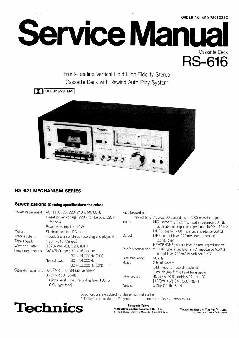
Technics RS 616 Service Manual

This is the 18 pages manual for Technics RS 616 Service Manual.
Read or download the pdf for free. If you want to contribute, please mail your pdfs to info@audioservicemanuals.com.

Page: 1 / 18
left right
Technics RS 616 Service Manual

Extracted text from Technics RS 616 Service Manual (Ocr-read)


Page 1

ORDER NO. ARD-7806038C

Service Manual

Cassette Deck

RS-616

Front-Loading Vertical Hold High Fidelity Stereo
Cassette Deck with Rewind Auto Play System

[1:]-

RS-631 MECHANISM SERIES

Specifications (Catalog specifications for sales)

Power requirement:

Motor:

Track system'
Tape speed:

Wow and flutter
Frequency response

Signaltornoise ratio:

AC,110/125/220/240V,50/60Hz

Preset power voltage; 220V for Europe, 125V
tor ASia

Power consumption: 10W

Electronic control DC motor

4»track 2-channel stereo recording and playback

4 8cm/s (177/8 ipsv)

0.07% (WRMS), 0.2% (DlN)

CrO2/FeCr tape; 30 ~ 16,000 Hz

30 ~ 14,000 Hz (DlN)

30~ 14,000 Hz

30~13,000Hz (DIN)

DolbyNR in; 66 dB (above SkHz)

Dolby NR out; 56dB
(Signal level :max. recording level, FeCr or
Cr02 type tape)

Normal tape;

Fast forward and
rewind time

lnput

Output:

Rec/pb connection:
Bias frequency.

Head

Dimensions

Weight

Approx. 90 seconds with C60 cassette tape
MIC; sensitivity 025 mV, input impedance 10 K9,
applicable microphone impedance 40052~ 10 K52
LINE; sensitivity 60 mV, input impedance 56 K52
LINE, output level 420mV, load impedance
22 K52 over
HEADPHONE; output level 65 mV, impedance 852
5 P DlN type input level 8mV, impedawce 5,6K52,
output level 420mV, impedance 1K2
90kHz
2-head system
1ALH head for record/playback
1-double7gap terrlte head for erasure
46cm(W)><15cm(H)><27.1cm(D)
[18"(W)><6"(H)><1073/4"(D) ]
52kg (11 lbs 8 oz)

Specifications are subject to change Without notice.
* Dolby and the doublerD symbol are trademarks of Dolby Laboatories

Technics

Panasonic Tokyo

Matsushita Electric Industrial Co., Ltd.
1745,67chome Shinbashl, Minaloku TokyolDS Japan

Matsushita Electric 773' ing Co., Ltd.
PO Box 2821, 0mm Osaka Japan

Page 2

Fig.

(D Power switch

® Cassette compartment door
6!) Tape counter and reset button
0 Recording indication iamp
© Levei meters

© Headphones Jack

® Pause button

Record button

© Piay button

69 Rewind/rewew button

GD Fast forward/cue button

(2) Stop button

4.

LOCATION OF CONTROLS
AND COMPONENTS

@@

Eject button
Timer standby button
input seiector
Doiby noiserreduction SWitch
Bias seiector
Equahzation seiector
@i input Ievel controls
Microphone iacks
7? Line output jacks
Record/piayback connection socket
Line input Jacks

(:3

5)

@©@(

@7

@®(

Page 4

MEASUREMENT AND
ADJUSTMENT METHOD

NOTE:
1. Make sure heads are clean.

2 Make sure capstan and pressure roller are clean.
3. Judgeable room temperature: 20i5°C (68i9°F)

4 Dolby NR switch' OUT
5 Blas selector: LOW
6 Equalizer selector' 120pS

ITEM

MEASUREMENT & ADJUSTMENT

REMARKS

Pressure of pressure roller
Equipment:
' Tensron gauge (max. 500 gr)

Takeup tension

Equlpment:
' Cassette torque meter
QZZSRKCT

1 Place UNlT into playback mode

2 Hook the tensron gauge to pressure roller lever and pull it in the dlreC'
tlon ot the arrow as shown ln tlg 9.

3 Measure the tension at the moment when the pressure roller moves
away from the capstan

Standard value: 400 i 50 gr

Adjustment method

Bend the part (A) of the pressure roller sprlng ln elther dlrectlon shown
by the arrow until the correct pressure lS attained

1. Mount cassette torque meter on UNIT
2. Place UNlT into playback mode and read takeup torque,
3. Measure several times and determine the mean value.

Standard value: 50 i20gr-cm

* Playback mode

*Tension
gauge

Pressure
roller

' Playback mode

Head azimuth adjustment

Equipment

* VTVM

Oscrlloscope

* Test tape (azrmuth)
QZZCFM

Record/playback head adjustment
1 Test equipment connection is shown below

LINE OUT 1-\ i--.
0% m
0 (<3) 0
Test tape Playback made VTVM Oscilloscope
Fig. 10

2. Play azimuth tape (QZZCFM 8kHz).

3. Adjust record/playback head angle adjustment screw (B) in hr; 11 so
that output level at LINE OUT becomes maxrmum.

4. Measure both channels, and adjust levels for equal output

5. After adjustment lock head adjustment screw wlth lacquer

. Playback mode

Record/playback
head