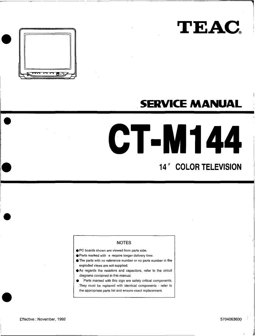
Teac CT M144 Service Manual

This is the 42 pages manual for Teac CT M144 Service Manual.
Read or download the pdf for free. If you want to contribute, please mail your pdfs to info@audioservicemanuals.com.

Page: 1 / 42
left right
Teac CT M144 Service Manual

Extracted text from Teac CT M144 Service Manual (Ocr-read)


Page 1

Effective : November, 1992

TEAC®

SERVICE MANUAL

CT-M144

14 COLOR TELEVISION

NOTES

.PC boards shown are viewed from parts side.

.Parts marked with >1: require longer delivery time.

.The parts with no reference number or no parts number in the
exploded views are not supplied.

.As regards the resistors and capacitors. refer to the circuit
diagrams contained in this manual.

0 \Parts marked with this Sign are safety critical components.
,They must be replaced with identical components - refer to
the appropriate parts list and ensure exact replacement.

5704063609

A .1

Page 2

TABLE OF CONTENTS

General Specifications .............. 1-1
Performance Specifications .......... 2-1
important Safety Precautions ......... 3-1
Disassembly Instructions ............ 4-1
Electrical Adjustment instructions ...... 5-1
Block Diagram ..................... 6-1
Schematic Diagram / PCB. and

Test Points ..... 7-1

Electrical Parts List ................. 8-1
Waveform Photogaraphs ............ 9-1
Voltage Charts ................... 10-1
Wiring Diagram ................... 1H
Cabinet Exploded View ............. 12-1
Cabinet Parts List ................. 13-1
Packing Exploded View ............. 14-1
Included Accessories &

Packing Parts List ........ 15-1

L74560VR

Page 10

DISASSEMBLY INSTRUCTIONS

General Note: "P.C.B." is abbreviation of "Printed Circuit Board".

1. DISASSEMBLY FLOW CHART

This flow chart indicates the disassembly steps of the cabinet parts and PCB. in order to gain access to item(s)
to be serviced. When reassembling, perlorm the step(s) in the reverse order. Bend, route and dress the cables as

they were originally.

Caution ! ; When removing the CRT, make sure to discharge Anode Lead of the CRT. Use the CRT
Ground Wire to discharge the CRT before removing the Anode Cap.

[1] Rear Cabinet

[2] CRT P.C.B. [3] Main P.C.B.
[5] CRT [4] IF P.C.B.
2. DISASSEMBLY METHOD
STEP REMOVAL
/LOC. PART FIG. REMOVE/*UNLOCK/ RELEASE/ UNPLUG/ UNCLAMP/ NOTE
NO. NO. DESOLDER
[1 Rear Cabinet CABt L2 (4pcs) 1
1 CARE
2 CRT P.C.B, CAB4 CN601,CN602,CN603,CN604 2
l 1 CABS FOCUS WIRE, SCREEN WIRE
3 Main PCB. CAB3 CN201,CN202,CN203,CN204,CN501 3
I 1 CABS ANODE CAP, FOCUS WIRE, SCREEN WIRE
41 IF P.C.B. . CAB3 CN101,CN102 4
45] CRT CAB4 Bz (4pcs) 5
4.1 L74SSDC