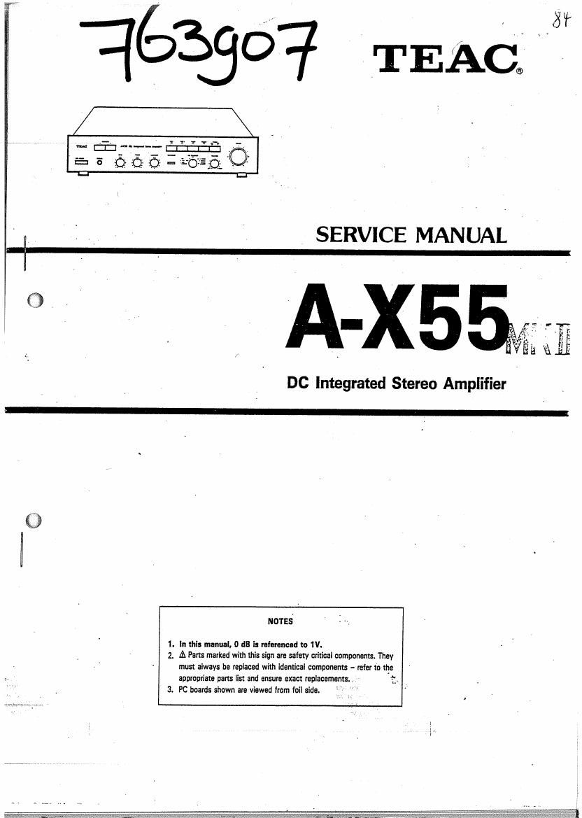
Teac AX 55 Service Manual

This is the 17 pages manual for Teac AX 55 Service Manual.
Read or download the pdf for free. If you want to contribute, please mail your pdfs to info@audioservicemanuals.com.

Page: 1 / 17
left right
Teac AX 55 Service Manual

Extracted text from Teac AX 55 Service Manual (Ocr-read)


Page 1

i :_ , SERVICE MANUAL '

_ A-xssr

DC Integrated Stereo Amplifier

NOTES

1. In this manual, 0 dB is micronced to 1V.

2, A Pans marked with Ihis sign are safety critical components. They
must always be replaced with identical components - refer to "1°
appropriate parts iist and ensure exact replacements. , t

3. PC boards shown are viewed from foil side.

Page 2

1 SPECIFICATIONS

Type DC Integrated Stereo Amplifier

Rated Output Power
(Both Channels, 8 ohms)
60W + 60W l1kHz, 0.03% T.H.D.)
55W+55W lZOHz-ZOkHz. 0.05% T.H.D.)

.TmaLl-larmonic. Distomon._.,.,.__,.,.,_..WLL_WW... , L,,,._..,..,..w-...

0.05% (20Hz-20kHz, at 55W+55W Output Power)
Output Bandwidth

IHF, -3dB, IOI-iz- SOKHz
Frequency Response

TUNER, CD/AUX, TAPE 1, 2, to SP out 5H2, 40kHz +0, ~3dE

PHONO to REC OUT, 20Hz- 20kHz+0 5:15 (RIAA)
Input Sensitivity

FHONO MC 0.24uV/100 ohms

FHONO MM 2.7mV/47K ohms . -

TUNER. CD/AUX. TAPE 1, 2,.150mV/47k ohms
Hated Output Voltage/impedance

TAPE REC I, 2, 150mV/47k ohms

2 ADJUSTMENT LOCATION
1-1 DC BALANCE CHECK
1. Connect the DC voltmeter to SPEAKERS A terminal.

2. Depress POWER switch to ON.
3. Confirm the DC voltmeter indication within 0 V :tZOmV.

1-2 IDLING CURRENT CHECK

3708.5 F

Signal- to-Noise Ratio
liHF A Network, short circuit)
PHONO MC 65dB
PHONO MM 75dB
TUNER. co/Aux, TAPE 1, 2, 94GB '

Tone 'Control
Bass 1-12d8. 100Hz
Treble 212dB, 10kl-Iz
High Filter IOkHz, -6dB
Power Requirements
10011201220l240 V AC 50/50 Hz, 240W (General Export Model)
220V AC 50Hz, 220W (Europe Model)
240V AC 50Hz, 240W lU.K./AUS. Model)
Dimensions [W x H x D)
435x80x255mm (17%"x33/Ia'x115/a')
Weight 7.6kg (16.72 lbs) net

- Improvements may result In specification or feature changes without
notice '

1-3 REALY OPERATION CHECK
1. Apply 1kHzl150mV i- 16. 5dB) to the CD/AUX terminal.

2. Adiust the VOLUME control so that output voltage' Is 10V at the

SPEAKER terminal
3. Shortcircuit the SPEAKER terminals between + and - so that the relay
RYI break immediately.

i
l
l

TVH601

POWER (11701

TRANSFORMER
PCB

SPEAKER
SWITCH PCB

INPUT
SELECTOR PCB
POWER

TONE

3 VOLTAGE CONVERSION

(FOR GENERAL EXPORT MODELS ONLY)

AC VOLTAGE SELECTION

/' This unit operates on 110 volts or 220 volts AC.
Before connecting the power cord to your AC outlet,
make sure that the setting position of this switch
matches your line voltage. if not, it must be set to
your voltage in accordance with the following directlon.

1. Connect the DC voltmeter between P9 to P10 and P11 to P12.
l 2. Confirm the DC voltmeter indication within 15mV when POWER is ON
' after 10 seconds.
i 3. if the DC voltmeter indicates over 25mV adjust the TVHGOI for LEFT
l channel or adiost the TVH701 for RIGHT channel on the MAIN PCB.
4. After the above procedures, allow 10 minites for the amplifier to warm
up completely.

110V 220V
Slide the switch to Slide the switch to
LEFT position as RIGHT position as
drawing as below drawing as below

AC SELECTOR

110V- !-'220V
-© Elm: ©