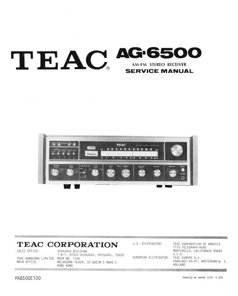
Teac AG 6500 Service Manual

This is the 38 pages manual for Teac AG 6500 Service Manual.
Read or download the pdf for free. If you want to contribute, please mail your pdfs to info@audioservicemanuals.com.

Page: 1 / 38
left right
Teac AG 6500 Service Manual

Extracted text from Teac AG 6500 Service Manual (Ocr-read)


Page 1

T E AG'6500
AM~FM STEREO RECEIVER
® SERVICE MANUAL


Tm - m u
u E'W'flfll-E'W-IWJM-M'm m

9- "'Fufi'am

.. STRIB TOR:
TEAC CORPORATION US 01 U IEQEIEIEEEIIIOIOEEW

MONTEBELLO, CALIFORNIA 90640

SALES OFFICE' SHINJUKU BUILDING
I-B-I, NISHlisHINJUKU, SHINJUKU) TOKYO [LS-A.

TEAC HONGKONG LIMITED ROOM N0. 05 EUROPEAN DISTRIBUTOR: TEAC EUROPE N.VI

MAIN OFFICE: MELBOURNE PLAZA. 33 QUEEN'S ROAD C, KABELNEG 45-47, AMSTERDAMM. 2,
HONG KONG HOLLAND

: din-1- I 2L m

PRINIED IN JAPAN 1072 S 002

MA6500E'100

Page 7

POWER AMPLIFIER

CURRENT ADJUSTING

The following procedure must be carried out on each channel with the
speaker terminals open, and with no signal applied to the input.

A 100 mA or higher meter is inserted between the power amplifier PC
board and DC power supply line, and the trimmer resistor (VR601/602)
on the PC board adjusted to obtain a 25 mA reading. First set the
trimmer fully counterclockwise and adjust until the meter indicates
25 mA.

After adjusting one channel, turn off the AC power, connect the meter
to other channel, apply the AC power and adjust as above.

Special attention is required as follows.

1. Remove AC power to the amplifier
before connecting or removing the
meter from the circuit. Failure
to do so may result in damage to
transistors.

2. Make small adjustments to the
trimmer resistor, do not move in
large increments.

DIOI

T

§

.1}._______-_ __

POWER AMPLIFIER REPAIRS

In case of power amplifier failure, a random voltage will appear at the
apeaker terminals. Acceptable voltage range at the speaker terminals is
0 plus or minus lOOmV. If voltage exceeds this limit the DC balance must
be restored to normal. Transistor failure is commonly the cause of un-
balance, check or replace the transistors in the order shown below until
the DC unbalance voltage is restored to limits. Perform these checks
with no load connected to the speaker terminals. After DC balance is re-
stored the idle current must be adjusted.

l. Q-60l-603 or Q-602-604

If a random voltage at the speaker terminals exceeds the permissible

range(0 to ilOOmV) for either channel, transistors Q-60l-603 or Q-602-

604 must be changed. These transistors must be replaced with matched

pairs of transistors having the same hFE value.

Q-605 or Q-606

0-609 or Q-6lO

If after performing steps 1, 2 and 3 the voltage at speaker terminals

is still excessive, replace all remaining transistors at the same time.

5. If speaker fuse blows, the most common causes are speaker leads shorted
or DC voltage imbalance in power amplifier stages. Check speaker leads
thoroughly before performing the above procedures.

6. Low output and increased distortion when volume is increased may be
caused by thyristor (D-751/752) failure in the electronic protective
circuit. In this case, setting volume control to maximum will cause
speaker fuse to blow.

DwN

Page 14

EXPLODED VIEW
AG- esoo