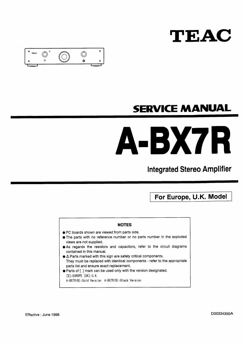
Teac A BX7R Service Manual

This is the 12 pages manual for Teac A BX7R Service Manual.
Read or download the pdf for free. If you want to contribute, please mail your pdfs to info@audioservicemanuals.com.

Page: 1 / 12
left right
Teac A BX7R Service Manual

Extracted text from Teac A BX7R Service Manual (Ocr-read)


Page 1

TEAC

Effective : June 1996

SERVICE MANUAL

A-BX7R

Integrated Stereo Amplifier

For Europe, UK. Model

NOTES

0 PC boards shown are viewed from parts side.

.The parts with no reference number or no parts number in the exploded
views are not supplied.

0 As regards the resistors and capacitors, refer to the circuit diagrams
contained in this manual.

0 A Parts marked with this sign are safety critical components.
They must be replaced with identical components - refer to the appropriate
pans list and ensure exact replacement.

0 Paris of l ] mark can be used only with the version designated,
[E] :EUROPE [UK] :U. K.
A-BX7R(N) :Gold Version A'BX7R(B):B|ack Version

000234300A

Page 2

A-BX7R

1 SPECIFICATIONS

Continuous Power Output (PMS):
50W+50W (20 - 20,000 Hz, 8 ohms)
70W+70W (20 , 20,000 Hz, 4 ohms)

Dynamlc Power Output (EIA):
56W (8 ohms)
82W (4 ohms)

Total Harmonlc Distortion:

0.015% (8 ohms)
0.03% (4 ohms)

Input Sensltlvlty/lmpedance:

CD, TUNER, AUX, TAPE: 300 mV/20k ohms
BALANCED (XLR): 1 V/Zok ohms

Signal-to-Nolse Ratlo (IHF A):

CD. TUNER, AUX, TAPE: 97 dB

Frequency Response:

CD, TUNER, AUX, TAPE, BALANCED:
20 - 40,000 Hz, - 1 dB
Power Requlrements/Power Consumptlon:
230 V AC. 50 HZ, 300 W
Dlmenslons (W x H x D):
443 X 103 X 381 mm

Welght (net): 96 kg

Standard Accessorles:

Wireless Remote Control Unit
(RC-591; for Gold-finish version or
RC-593; for Black-finish version) X 1 ,
AC cord x 1, Owners Manual X 1

O Improvements may result in specification or feature
changes without notice.

2 INSTALLATION OF PA-B1O

0 Disconnect power line cord.

1.

Using a hexagon-head tool, remove the top cover of
A-BX7R. Insert the Your spacers into the holes in the
main PCB_

Remove the tour jumpers on P3, one jumper P4 and
the one jumper on P2 (Pins 3 & 4) on the maln PCB.

. Connect the long wires connector of PA-B1o to P3, and

the short wlres connector to P2 on the main PCB.

. Fix the PA-B1o on the spacers using the four screws

provided.

.Before fixing the top cover again, select the right

position of SW1 (MM or MC) and SW2 (For MC
cartridges, the impedance set to 22 S2 or 100 S2 ) on
PA-B1o.

. Connect the turntable to the AUX terminals and GND

terminal of A-BX7R.


MAIN PCB