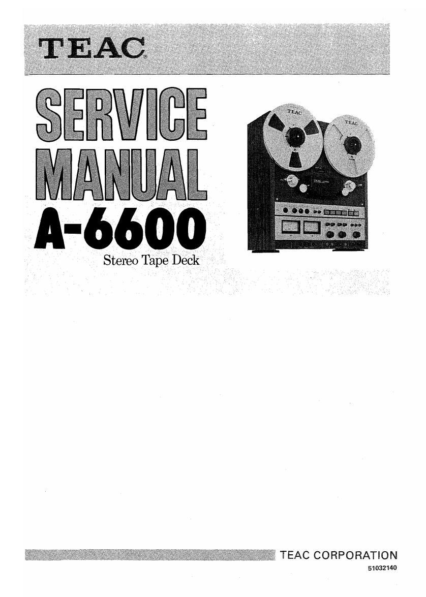
Teac A 6600 Service Manual

This is the 86 pages manual for Teac A 6600 Service Manual.
Read or download the pdf for free. If you want to contribute, please mail your pdfs to info@audioservicemanuals.com.

Page: 1 / 86
left right
Teac A 6600 Service Manual

Extracted text from Teac A 6600 Service Manual (Ocr-read)


Page 1

I: V _ Stereo Tape Deck ,

TEAC CORPORATION

51032140

Page 2

1. GENERAL DESCRIPTION

The TEAC A-6600 open reel tape deck is a 1/4 track, 2 channel (stereo) tape deck which has for-
ward record/play capability and also reverse play capability. The A-6600 operates at two selectable
Speeds, 7-1/2 ips and 3-3/4 ips. It can be used with reels up to a maximum 10-1/2" diameter. It
employs a DC Servo Controlled capstan motor and has dual pinch roller and capstan systems and

dual impedance rollers.

OxUIAWNH

10.

11.

- Table of Contents -

. GENERAL DESCRIPTION ................. 3

. SPECIFICATION AND SERVICE DATA ........ 4

. TOOLS FOR TESTING AND MAINTENANCE . . . . 5

. PARTIAL DIS-ASSEMBLY ................. 6

. TAPE TRANSPORT PARTS LOCATION ....... 11

. HEAD REPLACEMENT AND ALIGNMENT ..... 12
v Mechanical -

. MEASUREMENT AND ADJUSTMENT ........ 14
- Mechanical ~

. MEASUREMENT AND ADJUSTMENT ........ 18

- Electrical -
. SERVICING AND MAINTENANCE .......... 25

SIMPLIFIED SCHEMATIC AND LEVEL
DIAGRAMS .......................... 26

THEORY OF OPERATION ................ 27

Page 18

8~2 ADJUSTMENT SEQUENCE CHART

PLAYBACK HEAD _ OUTPUT LEVEL __ VU METER FWD/REV PLAY FREQUENCY RESPONSE SIGNALvTO-NOISE
AZIMUTH ADI. SETTING LEVEL SETTING DIFFERENCE LEVEL -PLAYBACK » RATIO rPLAYBACK r
BIAS RECORD HEAD BIAS TRAP PEAK LEVEL MIC INPUT LEVEL MONITOR LEVEL __ HEADPHONE
Apr AZIMUTH ADJ. Apr INDICATOR CHECK CHECK SETTING OUTPUT CHECK
RECORD LEVEL FREQUENCY RESPONSE SIGNAL-TDNDlSE __ MONOPHDNIC __ OII'IMU'M CROSSTALK CHANNEL _ DISTORT|0N
S 70VERALL- RATIO 'DVEKALLr RECORDING ERASURE REJECTION SEPARATION CHECK

Fig. 8-2 Adjustment Sequence Chart

8.

3 PLAYBACK HEAD AZIMUTH ADJ.

NOTE: Before proceeding with the following head align-

Awwpr

ments be sure that heads have been properly
mounted as to HEIGHT, TILT and TANGENCY.

See page 12.
MONITOR SW ........ TAPE CAL
SPEED Selector SW . . . . HIGH (7-1/2 ips)
REEL Size Selector SW . . SMALL
TRIM controls (L and R) . Click position (center)
OUTPUT Level Control . . 0 VU
Fine Adjustmentr

i Connect a VTVM to the OUTPUT jacks.

. Remove the Head Housing by removing 2 screws.

. Thread the TEAC YTT-1003 Test Tape on the deck.

. Play (>) the 16 kHz/-10 dB test tone in section 2 of

the test tape,

. Slowly rotate the Azimuth screw until maximum signal

is read on the VTVM.

. Connect an oscilloscope to the OUTPUT jacks.
. Adjust the azimuth screw (if necessary) until the oscillo-

scope shows that the signals are less than 45° out of
phase for 18 kHz signal. Check this using the 18 kHz
signal from the frequency response section of the test
tape.

i Secure the screw with a drop of locking paint.
. Depress the (4) button and turn the azimuth adjusting

screw for the reverse playback head (see Fig. 6-2 )for
maximum indication on the VTVM. Repeat steps 6 to
8 above for reverse playback head.

PLA YBA CK PERFORMANCE

8-4 OUTPUT LEVEL SETTING
- SPECIFIED OUTPUT LEVEL -

10.

11.

12.

Play the 400 Hz/O dB tone in section 1 of the YTT-1003
Test Tape.

Set the reference mark of the OUTPUT Level Control to
the 8 (0 VU) position.

Adjust P.B LEVEL R393/394 for 5 dB (435 mV) at
OUTPUT jacks.

- MAX. OUTPUT LEVEL -

l3.

14.

Turn the OUTPUT Level Control fully clockwise (max.)
and check for +l dB :2 dB at OUTPUTjacks.

Reduce OUTPUT Level Control until -5 dB (435 mV)
is obtained on the output VTVM.

NOTE: This is the Specified Output level setting. Do not

disturb this setting until the remaining adjustments
have been completed.

The minimum TRIM controls limits are :32 dB from
click position.

OSCILLOSCOPE

O
0
® 0 AMPL SPKFJ
O
ooo fl
o o o
V
via an
VTVM
DECK
at i J
under TEST #0
[W O O

v-xesrz

Fig. 83 Head Alignment Fine Adjustment Set-up emf
Test Connections (PLAYBACK)

Page 39

2 MOTION SENSING

This deck is designed so that, during Fast Wind mode,
STOP button is depressed then, immediately after which
Forward or Reverse button is pressed down, the deck, after
tape motion is completely halted, will conduct next opera-
tion, Forward Play or Reverse Play.

Motion Sensing circuit is designed for detecting whether
this tape is completely stopped or not, and then controlling
the next operation.

2-1 MOTION SENSING SIGNAL GENERATING
CIRCUIT

Ring Magnet shown in Fig. 21 is installed on Guide Roller
shaft on tape transport. Since Guide Roller does not rotate
while deck is in STOP state, Ring Magnet mounted on its
shaft will also be stopped. As a consequence, Magnetic
Resistance Element will not generate a signal. Therefore
Q751 does not operate, that is, does not amplify the signal,
and Q752 is in OFF state. C757 and C754 are charged and
Q753 is in ON state. During each Play, Fast Forward and
Rewind mode, Ring Magnet is rotating and a signal is gener»
ated by Magnetic Resistance Element. This signal will be

Due to output from Q751, Q752 goes ON-OFF repeatedly.
For this reason, electric charges on C757 and C754 are
discharged; and because base potential of Q753 is L while
Q752 goes repeatedly ON and OFF, Q753 will be switched
OFF. As a result of this, output from 0753 collector will
go into H while Guide Roller is turning (in other words tape
is moving) and will go L while deck is stopped. See Fig. 23
for Timing Chart of this section.

amplified by Q751.
I I
+24v
wégfifimg | R752 $2754 R767. ' MOTION SENSING
5,345," I ark :-3ak ISK: R75, 0753 SIG. our
\ I (2) IO? 735N I (TO CONTROL sue
Rm C756 0752 - R753 n V. IN or to)
f i, I seek 22/1215v p W 0759 I
I:. 0755 " .
5 I I I 22/25v Q5 I
(NON I ' :: .. meg: l
s ' -| | , R765 : 113757 0757 c154 I0k<
'-I I R7eg=- 0751 no» > 33 47 I
RING ' 52 /25v /25v
' I
MAGNET L- -- I I
7 I
I
I7 Emu: wag ______________ 4
Fig. 21

2-2 MOTION SENSING CONTROL SECTION

See Fig. 22. At U6 input terminal, L is applied when in Fast
Wind mode, and H when in the other modes. Now suppose
that deck is changed from STOP or PLAY mode to Fast
Wind mode, then since U6 input goes L, 0521 will go to
OFF state. Current flowing through R542, C521, D615 and
Q523 turns ON Q523 for a certain time.

Also, current flowing through R542, R543 and 0522
makes Q522 go ON. Emitter currents of 0522 and 0523

charge C522, and then raise base potential of Q524. When
Base potential at QS24 increases past a certain value, 0524
will go to ON state then Q525 will go to OFF state, finally
Q526 will be switched ON.

As a result of this, output terminal of U6 goes into L, thus
sending out the signal which is necessary for Fast Wind
mode.

_Ui ,,,,,,,,,,,
_______________ j
2 ° OUTPUT
9542 : R544 Rsasé R545
I I2k - c521 22" Ik 2
I/ V
I 35 05;? rd
I R543 3 0523
I $2 05220 _R7I5
max
I D52I 052 B R5047 v
I It
mpur D-H-M-g 1: m
I R5554; oeIe %
I Tcsza
I 959/
W CI 0588
L ,,,,,,,,,,,

CONTROL SIG IN (FROM 0573)

Fig. 22

40