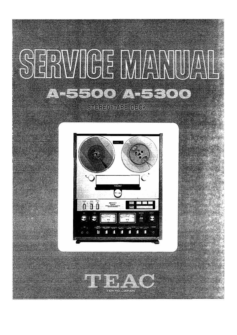
Teac A 5300 Service Manual

This is the 109 pages manual for Teac A 5300 Service Manual.
Read or download the pdf for free. If you want to contribute, please mail your pdfs to info@audioservicemanuals.com.

Page: 1 / 109
left right
Teac A 5300 Service Manual

Extracted text from Teac A 5300 Service Manual (Ocr-read)


Page 2

NOTE

This Service Manual was written for both the A-SSOO and the
A-SSOO Stereo Tape Decks because of their strong similarity
and common transport unit. The Amplifier unit, however, is
greatly dis-similar. Therefore, two separate Electrical
Adjustment Sections are included in this Manual, one for the
A-SSOO only and another for the A-SSOO only. Please distin-
guish between them for the type of deck being serviced.

When placing an order for parts, please refer to the PARTS LIST
and PRICE LIST FOR PARTS which are printed separately from this
manual.

1. File the PARTS LIST manual together with this SERVICE MANUAL;
further MANUAL CHANGE SHEETS should also be kept with these.

2. Use the PARTS LIST manual and the PRICE LIST FOR PARTS when
ordering replacement parts from TEAC Corp.

*"Dolby", "Dolbylized and the Double-D " m are trade marks of Dolby
Laboratories, Inc.

Page 25

SPECIFIED OUTPUT LEVEL SETTING

oscilloscope
PLAYBACK
° ° AMPLIFIER
OVOH?
<-
OUTPUT
.0 [a
a.
.5
RECORD H
AF 050 AMPLIFIER :2
LINE IN E"
N -> O
_ 2
-L// ' H
D d -- E
uring Recor Azimuth Adjustment, " o
the oscilloscope pattern angle for BIAS OSC " :4]
SOURCE and TAPE monitoring must N n X
be identical in order to maintain
a 0" phase difference between them. ._
Fig. 11-1 Fine Adjustment Set-up K)

~Head Alignment-

NOTE: Connect a 10 kn load resistor to the OUTPUT jacks for all
audio measurements when not using TEAC Test-Set (NI-826A) .

Forward play L p ):

hUINH

Ul

KOOOVO"

Place the MONITOR switch to the TAPE position.

Turn the OUTPUT control fully clockwise (MAX).

Thread TEAC Test Tape YTT-1003 on the unit. Operate at 19 cm-7-l/Zips.
Play the 400 Hz in Section 1 of the Test Tape. This tone is recorded
at operating reference level (1% of the TED level).

Adjust PLAY LEVEL VR-601/602 for approx. 580 mV at the Test Point (T-P)
on the DOLBY DECODER PC Board, using a VTVM (1 M1 or over).

. Depress (4 ) Reverse play button.

Adjust PLAY LEVEL VR-603/604 as in Forward play mode.

Return to Forward Play mode.

Align the reference marks of the OUTPUT controls to the 4 o'clock
position. This will give approximately -8 dB at the OUTPUT jacks.

OUTPUT
MORTANT: This is the Specified Output
Level setting. Do not disturb this set-
ting until the remaining adjustments have
been completed; Mark with 'Memory Marker".

Mallory Marker

Fig. 11-2 Specified OUTPUT position

..23..

Page 27

PHONES OUTPUT CHECK

1. Place OUTPUT control at the Specified level setting
[400 Hz signal at -8 dB].

2. Connect an 80 non-inductive resistor across the headphone jacks.
Connect Test-Set across the resistor.

3. Test-Set should indicate -24 dB :1 dB.

MINIMUM INPUT LEVEL SETTINGi

1. Connect an AF oscillator to the LINE IN jacks.
2. Place NDNITOR switch in SOURCE, RECORD EQ and BIAS switches
in HIGH position, and MODE L, R in ON position.
3. Apply a 400 Hz signal -18 dB to the LINE IN jacks.
4. Turn LINE control fully Clockwise (MAX) . Adjust VR-4Sl/452
on the MIC MIXING PC BOARD for approx. 580 mV at the Test Point
(T -P] on the DOLBY ENCODER PC BOARD (Left and Right channel) .
5. Check for -8 dB at the OUTPUT jacks.

DOLBY ENCODER
L R

0 GAIN 0 GAIN

Fig. 11-5 530 mV Test Points (DOLBY ENCODER PC BOARD)

SPECIFIED INPUT LEVEL SETTING

6. Apply a 400 Hz signal at -8 dB to the LINE IN jacks.
7. Adjust the LINE control for -8 dB at the OUTPUT jacks.

NOTE: Do not disturb the Specified Input Level position on these
controls until the remaining checks and adjustments are completed.
The difference between the channels must not exceed i2 dB as in-
dicate on the Test-Set. Adjust VR-451/452 (L-ch/R-ch) for identical
Levels.

VU METER LEVEL SET

Verify OUIPUT Controls at the Specified Output Level.

8. Place the NDNITOR switch to the SOURCE position.

9. Apply a 400 Hz signal at -8 dB to the LINE IN jacks.

10. Adjust VR-351/352 (METER PHONE PC BOARD) for 0 W on
the W meter.

_25_