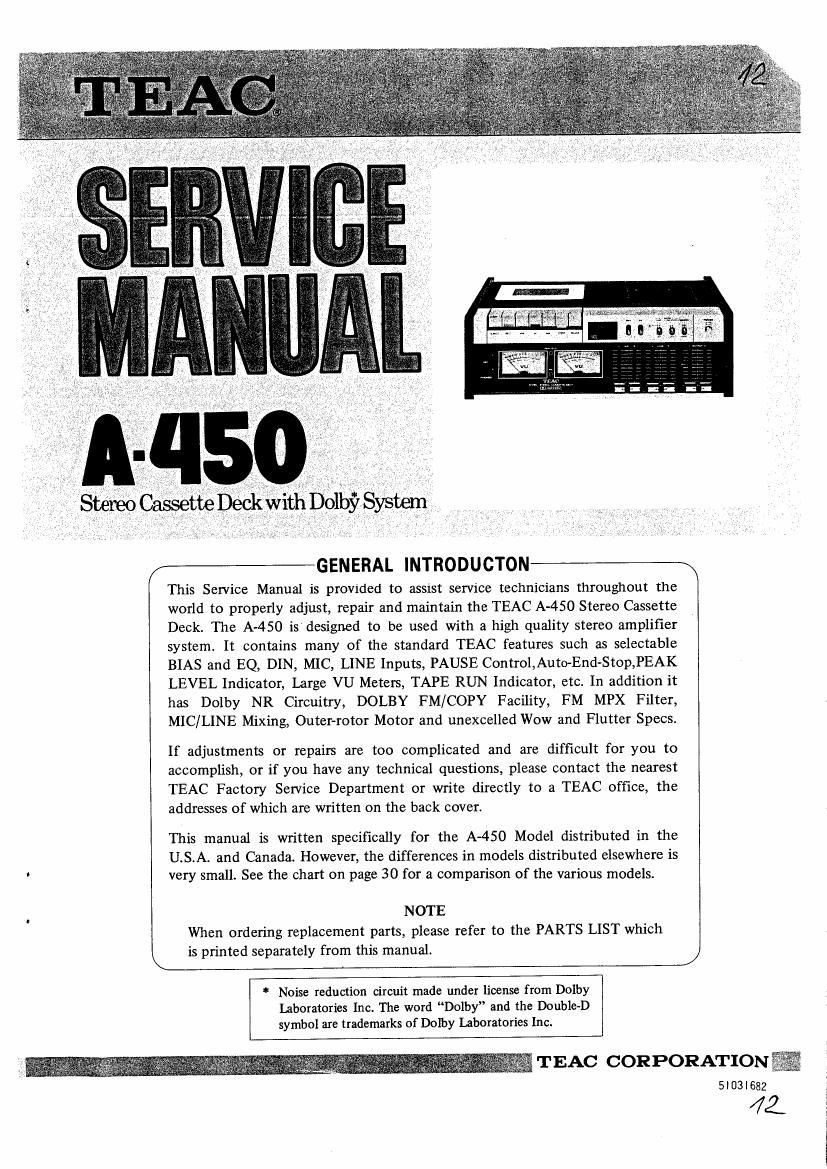
Teac A 450 Service Manual

This is the 58 pages manual for Teac A 450 Service Manual.
Read or download the pdf for free. If you want to contribute, please mail your pdfs to info@audioservicemanuals.com.

Page: 1 / 58
left right
Teac A 450 Service Manual

Extracted text from Teac A 450 Service Manual (Ocr-read)


Page 1

\

This Service Manual is provided to assist service technicians throughout the
world to properly adjust, repair and maintain the TEAC A-450 Stereo Cassette
Deck. The A-450 is designed to be used with a high quality stereo amplifier
system. It contains many of the standard TEAC features such as selectable
BIAS and EQ, DIN, MIC, LINE Inputs, PAUSE Control,AutoEnd-Stop,PEAK
LEVEL Indicator, Large VU Meters, TAPE RUN Indicator, etc. In addition it
has Dolby NR Circuitry, DOLBY FM/COPY Facility, FM MPX Filter,
MIC/LINE Mixing, Outer-rotor Motor and unexcelled Wow and Flutter Specs.

If adjustments or repairs are too complicated and are difficult for you to
accomplish, or if you have any technical questions, please contact the nearest
TEAC Factory Service Department or write directly to a TEAC office, the
addresses of which are written on the back cover.

This manual is written specifically for the A450 Model distributed in the
U.S.A. and Canada. However, the differences in models distributed elsewhere is
very small. See the chart on page 30 for a comparison of the various models.

NOTE
When ordering replacement parts, please refer to the PARTS LIST which
is printed separately from this manual.

* Noise reduction circuit made under license from Dolby
laboratories Inc. The word Dolby and the Double-D
symbol are trademarks of Dolby Laboratories Inc.

J

TEAC CORPORATION%

5l03l682

41

Page 2

CONTENTS


Specifications & Service Data .............. 3 7-1-1. Record/Playback Head
Azimuth Adjustments .......... 17
Test Equipment Required ................ 4 7-1-2. Specified Output Level Setting ...... 17
7-1-3. VUMeter Calibration -P1ayback- . . . . 18
.............. 4
TEAC Te Tape 7-1-4. Frequency Response -P1ayback- . . . . 18
. . . 7-1-5. Signal to Noise Ratio -P1ayback- . . . . 18
Partial Dis-assembly of Mam Parts ............ 5 7-1-6. Headphone Output Level Checks . . . . 19
3'1- Case/ Front Panel -------------- 6 7-2. Monitor Performance ............ 19
3-2- Motor ...................... 6 7-2-1. Minimum Input Level Checks ...... 19
3-3. Cassette Holder ................ 7 7-2-2, Specified LINE Control Setting . _ . . 20
3-4. Head/Pinch Roller .............. 7 7.2.3_ DOLBY m/copy CAL
3-4A. Head ...................... 7 Control Setting ................ 20
3-43. Pinch Roller .................. 7 7-2-4. VU Meter Calibration -Record- ...... 20
3-5. Brake Bracket ................ 8 7-2-5. LED Peak Level Indicator
3.5. Capstan Drive Assy/Dn've Belt ______ 8 Calibration .................. 20
3.7_ Reel Table __________________ 9 7-2-6. Dolby NR Effect Measurement . . . . 21
3-8. F t W' d R 11 As .......... 10 7-2-7- Dolby FM Compensator
as in 0 er sy Efficiency Checks .............. 21
3-9. Power Transformer ............ 10 d' f
e10. Play Idler Assy ................ 11 7'3 R? 3 P9? mam - ~ ------- 22
7-3-1. Bias Trap Adjustments .......... 22
Mechanical Checks and Adjustmenrs .......... 11 73'2 Record Bias Setting """""" 22
7-3-3. Record Level Setting ............ 23
- Pmh R011" 5 ------------ 11 7-3-4. Distortion Checks .............. 23
42' Take-Up Torque """"""" 12 7-3-5. Frequency Response -Overa]1- ...... 24
:3. East-For¥ard Torque ............ 1: 7-3-6. Signal to Noise Ratio -0verall- ______ 24
' ewmd orque """""""" 7-3-7. Erase Efficiency .............. 25
Torque Measurement using 7~3-8. Channel Separation ............ 26
The Cassette Torque Meter ------- 13 7-3-9. Adjacent Track Crosstalk Measurement 26
4-5. Brake Tension ................ 13 7-4. Adjustment Location ............ 27
46. Tape Speed/Wow and Flutter ...... l4 _
4.5.1. Tape Speed .................. 14 8. Level Diagram ........................ 28
4-6-2. Wow and Flutter .............. 14
9. Trouble-Shooting ...................... 29
Parts Location ........................ 15
10. Model Differences Comparison Chart ........ 30
hibrication .......................... 16 10.1_ Functional Difference Table ,,,,,, 30
6-1. Motor ...................... 16 10'2- Electrical Alignment Section ------ 30
6-2. Capstan Assy ................ 16 10'3- Frequency &Voltage ConVflSiOH - . ~ - 31
6-3. Flywheel Assy ................ 16
Electrical Checks and Adjustments .......... 16
7-1. Playback Performance .......... 17
it?) :1 u E El " N 1
mus-.31 ILm-LLLEQB 888 ° is»
9 o w
- f3 1 9
_ O

. .
410mmue 93")
445mm (I7 Ixg")

i

n-ou.

Fig. 1-1 A450 Dimensions