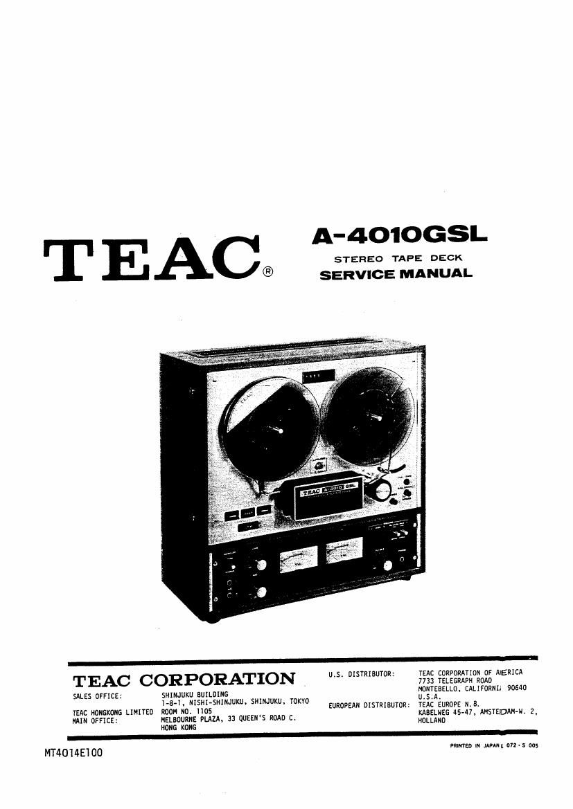
Teac A 4010 GSL Service Manual

This is the 72 pages manual for Teac A 4010 GSL Service Manual.
Read or download the pdf for free. If you want to contribute, please mail your pdfs to info@audioservicemanuals.com.

Page: 1 / 72
left right
Teac A 4010 GSL Service Manual

Extracted text from Teac A 4010 GSL Service Manual (Ocr-read)


Page 1

T EAC®

TEAC CORPORATION

SALES OFFICE: SHINJUKU BUILDING
I-B-I. NISHI-SHINJUKU, SHIHJUKU, TOKVO

YEAC HONGKDNG LIMITED ROOM ND. 1105
MAIN OFFICE: MELBOURNE PLAZA, 33 QUEEN'S ROAD C.

HONG KONG

MT4014E'IOO

A-401OGSL

STEREO TAPE DECK
SERVICE MANUAL

U.5I DISTRIBUTOR:

EUROPEAN DISTRIBUTOR:

TEAC CORPORATION OF NERICA
7733 TELEGRAPH ROAD
MONTEEELLO, CALIFORNIA 90640

U.S.A.

TEAC EUROPE N.B.

KABELNEG 45-47, AMSTEIDAMN. 2I
HOLLAND

PRINTED IN JAPAN[ U72 ' S 005

Page 2

SCOPE

This service manual provides adjustment and alignment procedures,
schematic diagram and parts replacement information and the prop-
er procedures for obtaining necessary repair parts.

If adjustments or repair procedures are not clear or seem diffi-
cult to accomplish or should you desire more detailed technical
information, please contact your nearest TEAC dealer. TEAC Corpo-
ration or affiliated corporations, address's of which are printed
in this manual.

TABLE OF CONTENTS

SL & GSL FUNCTIONAL-COMPARISON CHART
SERVICE DATA

TEST EQUIPMENT

PARTIAL DISASSEMBLY

HEADS ALIGNMENT -MECHANICAL-
MEASUREMENT AND ADJUSTMENT -MECHANICAL-
MEASUREMENT AND ADJUSTMENT -ELECTRICAL-
PREVENTIVE MAINTENANCE

TROUBLE SHOOTING

WARRANTY AND SHIPPING INSTRUCTIONS
EXPLODED VIEW AND PARTS LIST

PRINTED CIRCUIT BOARD AND PARTS LIST
SCHEMATIC DIAGRAM

MANUAL CHANGE SHEET

OmeU'IgLAJNA

Page 26

BIAS ADJUSTMENT

NOTE: These adjustments are only made at 7-1/2ips tape speed, the
bias oscillator frequency is 100 kHz :5 kHz.

-HIGH position- i

1. Thread record test tape Scotch #203 on the unit and apply 400 Hz
/-8 dB to LINE IN jacks. ._
2. Place the BIAS, EQ/LEVEL switch to HIGH and place the unit in the _
record mode. Placenthe MONITOR switch in the TAPE position.
3. Adjust capacitor VC-102/202 for a peak on the level meter. Turn
the capacitors clockwise until a decrease of 0.5 dB is obtained.

-NORMAL position-

4. Thread record test tape Scotch
#150 on the unit.

5. Place the BIAS, EQ/LEVEL switch
to NORMAL and place the~unit in
the record mode.

6. Adjust capacitor VC-lOl/ZOl for
a peak on the level meter. Turn
the capacitors clockwise until
a decrease of 0.5 dB is obtained

7. After completing this adjustment,»
return BIAS, EQ/LEVEL switch to
HIGH position.


Fig. 6-11 Bias Characteristic

RECORD LEVEL SET :HIGH POSITION-

l. The OUTPUT controls must be at the specified output level posi-
tion (-8 dB at OUTPUT jacks) and set the BIAS, EQ/LEVEL switch
to HIGH position.

2. Apply a 500 Hz signal at -8 dB to the LINE IN jacks.
3. Place the unit in the record mode, the MONITOR switch in the

TAPE position.
4. While recording a 400 Hz signal on the Scotch #203 record test

tape, adjust VR-103/203 for a reading of O VU on the VU meter
(-8 dB at the OUTPUT jacks.)

RECORD LEVEL SET -NORMAL POSITION-

5. Set the BIAS, EQ/LEVEL switch to NORMAL position.
6. Using a Scotch #150 record test tape, record A00 Hz/-8 dB test

signal.
7. While recording this signal, adjust VR-lO9/209 for 0 VU on the .

VU meter.
8. After completing adjustment, return the BIAS, EQ/LEVEL switch

to HIGH position.

Page 28

LEVEL VARIATIONS

Using Scotch #203 test tape, recorded at the specified level setting
with BIAS switch in HIGH position, during record/playback the output
level variations should not exceed those shown in the below chart.

7-l/Zips: 0.5dB at 400Hz
m 1.0dB at IOkHz
3-3/41ps: l.OdB at SkHz

Fig. 6-lz Level Variation

OVERALL SIGNAL T0 NOISE RATIO

IMPORTANT: Clean and demagnetize the heads before proceeding. It
is extremely important that all tests described in the proceeding
paragraphs have been completed and that all controls adjusted are
left unaltered.

1. Thread 3 record test tape (Scotch #203) on the unit.
2. Remove the AF oscillator from the LINE IN jacks.
3. Place the unit in the record mode with no signal applied. BIAS,

EQ/LEVEL switch in HIGH position.

NOTE: Noise readings, when taken while recording, may be affected
by the bias signal which could be leakings through. It is there-
fore good practice to rewind the no signal recorded section and

take the noise reading during playback.

4. Note the point on the index counter where recording begins.

5. Rewind the tape and play it back.
6. The noise level as indicated on the level meter should be -55 dB or

less. This is equivalent to a 47 dB signal to noise ratio at oper-
ating reference level.

NOTE: Bias, erase and playback amplifier noise are all included in
in this measurement. All frequencies between 40 Hz and 15 kHz are

measured unweighted.

+15
+1!
+l5

5+

m
mum ll n: n-m.

Fig. 6-13 EQ. Curves -Record-