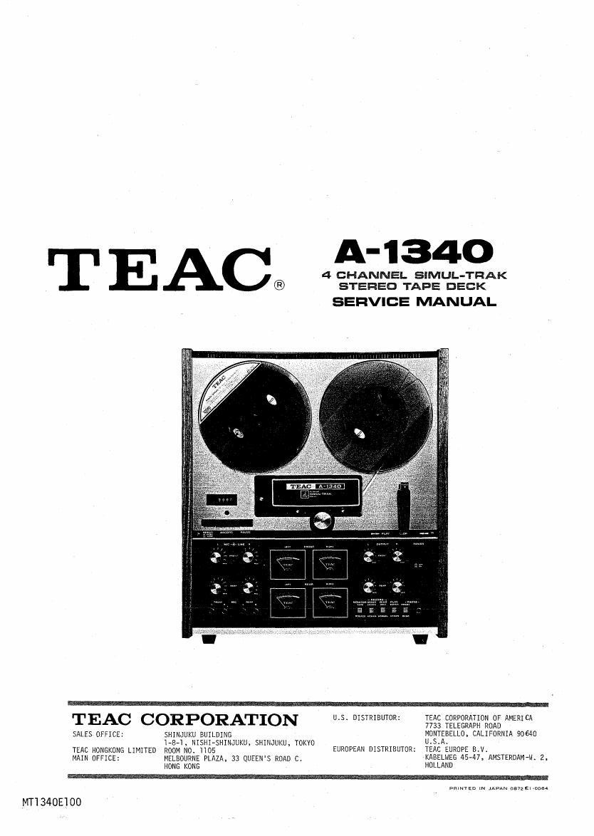
Teac A 1340 Service Manual

This is the 56 pages manual for Teac A 1340 Service Manual.
Read or download the pdf for free. If you want to contribute, please mail your pdfs to info@audioservicemanuals.com.

Page: 1 / 56
left right
Teac A 1340 Service Manual

Extracted text from Teac A 1340 Service Manual (Ocr-read)


Page 1

T E C A- 1340
A 4 CHANNEL SlMUL-TRAK
® STEREO TAPE DECK

SERVICE MANUAL

VEAC H r U.S. DISTRBIUTOR: :7. TEAC (IOORPAIHIONOF AMERICA

7733 TELEGRAPH ROAD

SALES OFFICE: SHINJUKU BUILDING MONTEBELLO, CALIFORNIA 90640
1-8-1, NISHIAsHINJUKU, SHINJUKU, TOKYO U.S.A.

TEAC HDNGKONG LIMITED ROOM N0, 1105 EUROPEAN DISTRIBUTOR: TEAC EUROPE B.V.

MAIN OFFICE: MELBOURNE PLAZA, 33 QUEEN'S ROAD C. KABELMEG 45-47, AMSTERDAM-N. 2.

HONG KONG HOLLAND

pmmzn IN JAPAN osvzeuaos.

MTI340E'IOO

Page 2

1 GENERAL DESCRIPTION

l.
2.
3.

5.
6.
7.
8.
9.
10.
ll.

INDEX

GENERAL DESCRIPTION

SERVICE DATA

EQUIPMENT REQUIRED

PARTIAL DISASSEMBLY

HEAD REPLACEMENT AND ALIGNMENT -MECHANICAL-
MEASUREMENT AND ADJUSTMENT -MECHANICAL-
MEASUREMENT AND ADJUSTMENT -ELECTRICAL-
SIMPLIFIED DIAGRAM (WITH VOLTAGE READINGS)
PREVENTIVE MAINTENANCE AND WARRANTY
TROUBLE SHOOTING

PACKING FOR SHIPMENT

SCHEMATIC DIAGRAMS

PRINTED CIRCUIT BOARD AND PARTS LIST
EXPLODED VIEW AND PARTS LIST

MANUAL CHANGES

Page 23

25

i assume in a

RECORD LEVEL SET

OVERALL

The OUTPUT controls must be at the specified output level position
(-8 dB at OUTPUT jacks).

FREQUENCY RESPONSE

Apply a 400 Hz signal at -8 dB to the LINE IN jack.

Thread record test tape SCOTCH 203 on the unit, then set the REC
BIAS switch to HIGH position.

Place the unit in the 4 CHAN RECORD MODE with the MONITOR switch
in the TAPE position, LINE controls fully clockwise.

Adju'st FRONT VR-301/401, REAR VR-70l/801 for -8 dB signal at
OUTPUT jacks.

HIGH position

Thread a blank SCOTCH 203 tape on unit, place BIAS switch

at HIGH, tape SPEED at HIGH, MONITOR switch at TAPE.

Apply a signal swept from 50 Hz to 15 kHz at -23 dB to LINE IN
jacks and record it on the test tape.

Adjust FRONT L-301/401, REAR L-701/801 for best response.(Fig.7-9).

. Repeat above procedures for 3-3/4ips using a signal swept from

50 Hz to 7.5 kHz.

NORMAL position

5.

6.

Thread a blank SCOTCH 150 tape on the unit. Place BIAS
switch at NORMAL position, tape SPEED at HIGH.
Repeat overall response check at both speeds.

NOTE

If there is more than 2 dB difference in frequency response
between 2-channel and 4-channel operation, adjust L-901/902
at 10 KHz,7-l/2 ips.

mums: m an

Boo

musncv m m """ wwmm m m M"

HIGH position NORMAL position

Fig. 7-9 Frequency Response limits -Record-

Page 27

9 PREVENTIVE MAINTENANCE

LUBRICATION INSTRUCTIONS

For maximum service life and optimum performance, lubricate the parts
listed below after every 2,000 hours of service. Use only a light
machine oil of good quality, such as TEAC'S TZ-262 or TZ-Z65.

Oil the motor through the oiling tube. Apply approximately lcc.
Apply 2 drops to the Idler Shaft bearings.

. Apply 2 drops to the Pinch Roller Shaft bearing.

. Apply 1 drop to the Index Counter relay pulley bearing.

. Apply a medium film of light machine grease to each roller surface
on the levers and cams. Avoid lubricating the brake areas.

U'ILUJNH

CAUTION
Do not over-lubricate. Wipe off all excess lubrication
with a cotton swab soaked in alcohol. Excess lubricating
fluids would be scattered during operation onto the rubber
components which deteriorate when soaked with oil.

Counter
Relay Pulley
O
I
O
0 :1 Drop Pinch Roller

mom.

Fig. 9-1 Lubrication Locations

29

Page 34

EXPLODED VIEW 2

A-I 340

ABOVE THE MAIN CHASSIS