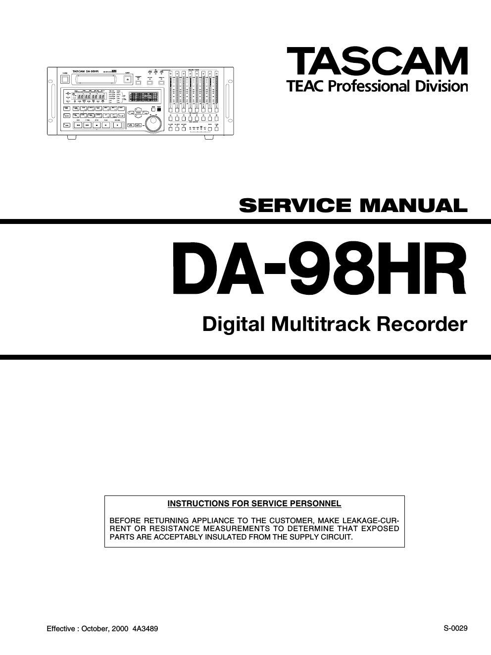
Tascam DA 98HR Service Manual

This is the 107 pages manual for Tascam DA 98HR Service Manual.
Read or download the pdf for free. If you want to contribute, please mail your pdfs to info@audioservicemanuals.com.

Page: 1 / 107
left right
Tascam DA 98HR Service Manual

Extracted text from Tascam DA 98HR Service Manual (Ocr-read)


Page 1

TASCAM

TEAC Professional Division

SERVICE MANUAL

DA-98HR

Digital Multitrack Recorder

BEFORE RETURNING APPLIANCE TO THE CUSTOMER, MAKE LEAKAGE-CUR-
RENT OR RESISTANCE MEASUREMENTS TO DETERMINE THAT EXPOSED
PARTS ARE ACCEPTABLY INSULATED FROM THE SUPPLY CIRCUIT.

INSTRUCTIONS FOR SERVICE PERSONNEL

Effective : October, 2000 4A3489

8-0029

Page 2

CONTENTS

1_ SPECIFICATIONS .............................. 3
2.TECHNICALINFORMATION ------~--nn----u7

2-1. Activation of test mode ---------------------- 7
2-2. Activation of VTR mode --------------------- 7
2-3. Displaying ROM version numbers ~~~~~~~~~~~~~ 7
2-4. Displaying SUB MPU version numbers - ~ - - 7
2-5. Displaying the voltage of battery ~~~~~~~~~~~~~~ 7
2-6. Displaying the hed drum utilized time ~~~~~~~~~~ 7
2-7. Displaying the servo error history ~~~~~~~~~~~~~~ 7
2-8. KEY PCB check mode ....................... 8
2-9. How to use the built-in oscillator ~ -
2-10. Removing the FRONT MPU ~~~~~~~~~~~~~~~~~ 8
2-11. Removing the SYS ROM ~~~~~~~~~~~~~~~~~~~~ 8
2-12. Checking the optional IF-AN98HR (A/D board
and D/A board) ........................... 9
2-13. Changeover of Reference level ~~~~~~~~~~~~~~ 9
2-14. EXTERNAL CONTROL l/O ----------------- 12
3. ASSEMBLING THE MECHANISM ASS'Y . ~ - . . - . - - 19
3-1. Flowchart of assembling -------------------- 19
3-2. Installation of the mechanical parts ~~~~~~~~~~~ 20
4. MECHANISM ADJUSTMENTS 26
4-1. Preparation .................... 27
4.2_ Test tape ................................. 27
4-3. Adjusting the tension arm position ~~~~~~~~~~~~ 28
4-4. Adjusting the torque ........................ 25
4-5. Adjusting the tape travel ~~~~~~~~~~~~~~~~~~~~ 29
4-6. Confirming the travel in F.FWD, REW and
REV mode ............................... 32
5. ELECTRICAL ADJUSTMENTS - - - - . - - - - ' ' ' - - - - -35
5-1. Check and adjustment points ~~~~~~~~~~~~~~~~ 35
5.2_ Test tape ................................. 36
5-3_ +5 V suppjy check ......................... 36
5-4. P.G. (Phase generator) position adjustment ~ ~ - ~ 36
5-5. Offset adjustment in the VCO free-running
frequency automatic compensation circuit ~~~~~ 37
5-6. Playback equalizer adjustment ~~~~~~~~~~~~~~~ 38
5.7_ RF level check ............................ 39
5-8. Playback error rate check - - - . 40
5-9. Recording current adjustment ~~~~~~~~~~~~~~~~ 41
5-10. Recording/playback RF level check ~~~~~~~~~~ 43
5-11. Recording/playback error rate check --------- 43

6. EXPLODED VIEWS AND PARTS LIST
7. PC BOARDS AND PARTS LIST
8. INCLUDED ACCESSORIES

...........45
..53

Efl

1111; .......................................... 3

2.5-7:7j)b4>77jx-=/3> ................... 7
2-1.7T-XFE- lefiéb ----------------------------- 7
2-2.VTR¥- muggy ............................... 7
2-3. ROM®I§A§3 yfifi .............


2»4. SUB mum/(~73 >§fx -- ~7
2-5. I\'-y-?U ngEfifl-V --------------
2-6. FfiAEléiiéfiflaFefiOE/fi ---------------------- 7
2-7. vafilaafimofifi ......................... 7
2-8. KEY P089117 7%7 l~" ........................ g
29. wasnwsworsmmz .......
2-10. FRONT MPurMi L75 -------------
2-11. svs ROMer b7:- ----------------------------- 8
2-12. 7T7) a y lF-AN98HR (A/Drri- F, D/Atie F)
(7);: ~y 7i::u.\( --------------------------- 9
Z13.'J77I/PXI/NJLUJEEKOVT ............ 9
2-14. EXTERNAL CONTROL I/Olzour -- .12
3_ x 71 Ass'Ymgfij ............................. 19
3-1.$Eި7n~-:Hvil~ -------------------------- 19
3-2. X figrammnw ------------------------------ 20
4_ mggfigg ................................... 26
4-1. iElirE-m
4-2. 7:2 I~7~7 ...............
4-3. 7)? a >7~Afi§§fi¥ ..................... 28
4-4. |~Jlx7§fi§g ..................................... 28
4-5. -? 7 jflfilfl -------------------------------- 29
4-6. FF, REW, REV REE Ffioifiiéiis ------------ 32
5. Efifiifig ................................... 35
5-1. ififlifififih; UEfiEEfifi ----------------------- 35
5.2. 5-2 |~7-#7 ................................... 35
5-3. Realé+5vm-§£ ------------
5-4. PG (Phase Generator) fifiafifi ---------------
5-5. V007 U -5 >l§ii§§ifi§lfilfl§lfi§
097nm rem ------------------------------ 37
56. air narfi~§R¥ ------------------------- 38
5-7. RFI/NwfiEEE .................................. 39
5-8. E$15~v~ bit/E533 ......
5-9. easiamem ---------
5-10. Eafifii RFI/NMEEE ........... 43
5»11.§B§ifi$l5~b# HEEE ------------------- 43
6.5}fl.tl\-yl}1|~ .......................... 45
Igfilt/t-yuzp .......................... 53