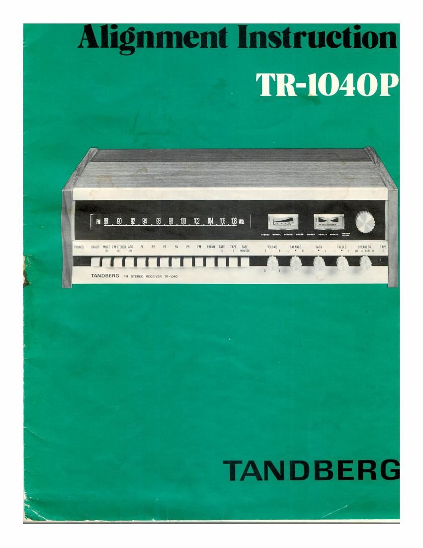
Tandberg TR 1040 Schematic

This is the 20 pages manual for Tandberg TR 1040 Schematic.
Read or download the pdf for free. If you want to contribute, please mail your pdfs to info@audioservicemanuals.com.

Page: 1 / 20
left right
Tandberg TR 1040 Schematic

Extracted text from Tandberg TR 1040 Schematic (Ocr-read)


Page 1

TR-IO40P

HMS nun muummninm Pl n P: n P5 In mun TAPE WE 1m vulUME nuns: BASS mm: SPEAKERS
r z z u - I - - . m I A-I I

E???

u an an v mum

TAN DBERG FM sYEfiEo RECEIVER YR-OMI

Page 2

1.0 ALIGNMENT OF
STEREO-DECODER

1.1 Complete alignment.

A complete alignment involves adjustment of

7 The decoder oscillator; 19 kHz (paragraph 1.2)
7 Channel separation (paragraph 1.2.1).

- 19 kHz filter (paragraph 1.2.2)

7 Stereo/mono switching threshold (paragraph 1.2.3)
- Definition: Pilotsignal 19 kHz (1 2 Hz).

The following equipment is needed for a complete
adjustment:

7 FM stereo generator

7 Oscilloscope with sensitivity 5 mV/cm

7 Frequency Counter

7 Selective voltmeter or a.c. voltmeter and 20 kHz low
pass filter

1.2.3 Stereo/mono switching threshold.

Apply a 10 pV signal from the FM stereo generator to the
75 ohm antenna input and adjust the generator for 10%
pilotsig-nal. Set R221 fully counterclockwise (seen from
the component side) and then turn R221 slowly clock-
wise until the stereo indicator lights up.

Note! If a FM stereo generator is not available an ordinary
FM generator can be used for this adjustment. In this case
it may be necessary to check the modulation frequency
(19 kHZ) with the frequency counter.

Alignment of F M-section

See the FM-alignment procedure in table and
the oscillograms.

Table, FM-alignment.

1.2 The decoder oscillator. 19 kHz.

Apply a 1 mV signal from the FM stereo generator,
unmodulated.

Adjust R808 so that the frequency counter connected
to MBOI indicates 19 kHz.

Alternative method: This adjustment can be carried out
without a frequency counter as follows: Apply a 1 mV
signal from the FM stereo generator, modulated with
10% pilotsignal.

Turn R808 slowly from one extreme to.the point where
the stereo indicator lights up. Turn further in the same
direction until the light goes out. Then turn in the
opposite direction to set R808 in the middle of the
range where the indicator lights.

1.2.1 Channel separation:

Apply a 1 mV signal to the antenna input from the FM
stereo generator and set the generator for 10% pilot
signal. Modulate the right channel with 1 kHz at

30% deviasjon. Connect the oscilloscope to the TAPE
OUT socket, of the left channel and adjust R840 to
minimum deflection.

Check this adjustment with the 1 kHz signal in the left
channel and measure the output of the right channel.

Alternative method: Adjust R840 for minimum signal in
the left (right) speaker when receiving a test FM stereo
transmission with signal in the right (left) channel only.

1.2.2 19 kHz filter.

Apply a 1 mV signal from the FM stereo generator to the
antenna input and set the generator for 10% pilotsignal.

Adjust R833 and R835 (R834 and R836) alternatively
for minimum signal at the left (right) TAPE OUT. Use a
selective voltmeter or an a.c. voltmeter with a low pass
filter at 20 kHz to avoid signal components at 38 kHz
causing a false indication.

Receiver
Step Alignment procedure Frequency Frequency
1 FM-oscillator
1A 25V for varicap
90 MHZ 90 .\le
18 FM-osc. (FM) 105 MHZ 105 MHz
87.5 MHZ 87.5 MHZ
1C FM-preset (P1) 105 MHZ 105 MHz
90 MHZ 90 MHZ
2 Aerial circuit 105 MHz 105 MHz
3 mar 90 MHz 90 MHz
4 Discriminator 90 MHZ 90 MHZ
5 Center tuning meter 90 MHZ 90 MHZ
Field strength
6 indicator 90 MHZ 90 MHZ
7 90 MHZ 90 MHz

Page 16

1.0 ALIGNMENT OF
STEREO-DECODER

1.1 Complete alignment.

A complete alignment involves adjustment of

7 The decoder oscillator; 19 kHz (paragraph 1.2)
7 Channel separation (paragraph 1.2.1).

- 19 kHz filter (paragraph 1.2.2)

7 Stereo/mono switching threshold (paragraph 1.2.3)
- Definition: Pilotsignal 19 kHz (1 2 Hz).

The following equipment is needed for a complete
adjustment:

7 FM stereo generator

7 Oscilloscope with sensitivity 5 mV/cm

7 Frequency Counter

7 Selective voltmeter or a.c. voltmeter and 20 kHz low
pass filter

1.2.3 Stereo/mono switching threshold.

Apply a 10 pV signal from the FM stereo generator to the
75 ohm antenna input and adjust the generator for 10%
pilotsig-nal. Set R221 fully counterclockwise (seen from
the component side) and then turn R221 slowly clock-
wise until the stereo indicator lights up.

Note! If a FM stereo generator is not available an ordinary
FM generator can be used for this adjustment. In this case
it may be necessary to check the modulation frequency
(19 kHZ) with the frequency counter.

Alignment of F M-section

See the FM-alignment procedure in table and
the oscillograms.

Table, FM-alignment.

1.2 The decoder oscillator. 19 kHz.

Apply a 1 mV signal from the FM stereo generator,
unmodulated.

Adjust R808 so that the frequency counter connected
to MBOI indicates 19 kHz.

Alternative method: This adjustment can be carried out
without a frequency counter as follows: Apply a 1 mV
signal from the FM stereo generator, modulated with
10% pilotsignal.

Turn R808 slowly from one extreme to.the point where
the stereo indicator lights up. Turn further in the same
direction until the light goes out. Then turn in the
opposite direction to set R808 in the middle of the
range where the indicator lights.

1.2.1 Channel separation:

Apply a 1 mV signal to the antenna input from the FM
stereo generator and set the generator for 10% pilot
signal. Modulate the right channel with 1 kHz at

30% deviasjon. Connect the oscilloscope to the TAPE
OUT socket, of the left channel and adjust R840 to
minimum deflection.

Check this adjustment with the 1 kHz signal in the left
channel and measure the output of the right channel.

Alternative method: Adjust R840 for minimum signal in
the left (right) speaker when receiving a test FM stereo
transmission with signal in the right (left) channel only.

1.2.2 19 kHz filter.

Apply a 1 mV signal from the FM stereo generator to the
antenna input and set the generator for 10% pilotsignal.

Adjust R833 and R835 (R834 and R836) alternatively
for minimum signal at the left (right) TAPE OUT. Use a
selective voltmeter or an a.c. voltmeter with a low pass
filter at 20 kHz to avoid signal components at 38 kHz
causing a false indication.

Receiver
Step Alignment procedure Frequency Frequency
1 FM-oscillator
1A 25V for varicap
90 MHZ 90 .\le
18 FM-osc. (FM) 105 MHZ 105 MHz
87.5 MHZ 87.5 MHZ
1C FM-preset (P1) 105 MHZ 105 MHz
90 MHZ 90 MHZ
2 Aerial circuit 105 MHz 105 MHz
3 mar 90 MHz 90 MHz
4 Discriminator 90 MHZ 90 MHZ
5 Center tuning meter 90 MHZ 90 MHZ
Field strength
6 indicator 90 MHZ 90 MHZ
7 90 MHZ 90 MHz