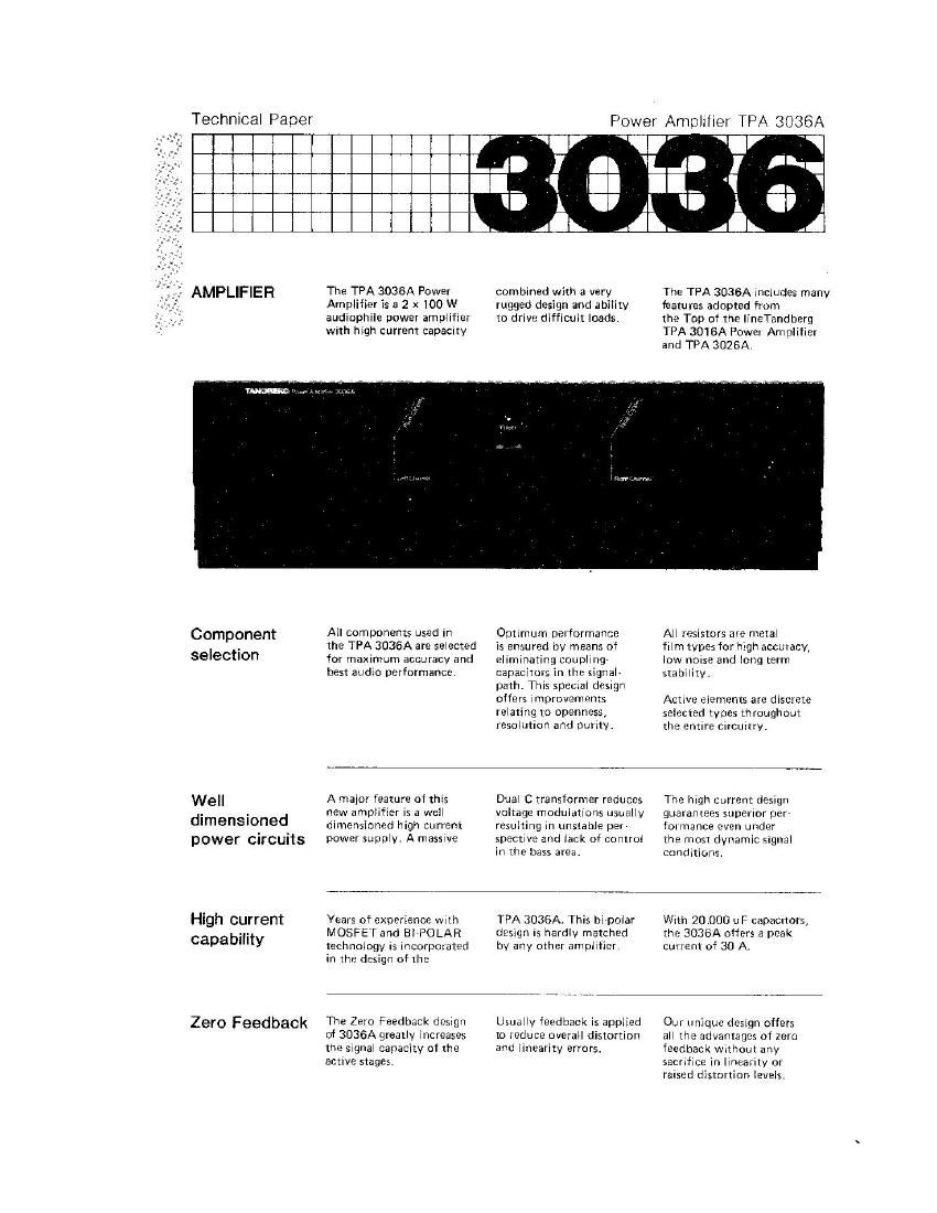
Tandberg TPA 3036 A Brochure

This is the 2 pages manual for Tandberg TPA 3036 A Brochure.
Read or download the pdf for free. If you want to contribute, please mail your pdfs to info@audioservicemanuals.com.

Page: 1 / 2
left right
Tandberg TPA 3036 A Brochure

Extracted text from Tandberg TPA 3036 A Brochure (Ocr-read)


Page 1

Power Amplifier TPA 3036A

AMPLIFIER

The TPA 3036A Power
Amplifier is a 2 x100 W
audiophile power amplifier
With high current capacrty

combined with a very
rugged design and ability
to drive difficult loads.

The TPA 3036A includes many
features adopted from

the Top of the linETandberg
TPA 3016A Power Amplifier
and TPA 3028A,

Component
selection

Well
dimensioned
power circuits

High current
capability

Zero Feedback

All components used in
the TPA 3036A are selected
for maximum accuracy and
best audio performance.

Optimum performance
is ensured by means of
eliminating coupling»
capacitors in the signal
path. This special design
offers improvements
relating to openness,
resolution and purity.

All resistors are metal

film types forhigh accuracy,
low noise and long term
stability.

Active elements are discrete
selected types throughout
the entire circuitry.

A major feature of this
new amplifier is a well
dimensioned high current
power supply. A massive

Dual C transformer reduces
voltage modulations usually
resulting in unstable per
spective and lack of control
in the bass area.

The high current design
guarantees superior perr
for mance even under
the most dynamic signal
conditions.

Years of experience With
MOSFET and BIPOLAR
technology is incorporated
in the design of the

The Zero Feedback design
of 3036A greatly increases
the signal capacity of the
active stages.

TPA 3036A. This bipolar
design IS hardly matched
by any other amplifier.

Usually feedback is applied
to reduce overall distortion
and linearity errors.

With 20.000 uF capaCitors,
the 3036A offers a peak
current oi 30 A.

Our unique dCSlgn offers
all the advantages of zero
feedback Without any
sacrifice in linearity or
raised distortion levels.

Page 2

Feed forward
driver design

Thermic
Servo Loop

The feed forward circuitry
eliminates the on-resistance
in the output transistors.

This results in extremely
low output impedance 7

all through the audio

hand up to several hundred
KHz - assuring iull control
over all elements in the

speakers, insuring a highly
detailed and accurate
midrange and highrend
performance.

DC stability is usually
controlled by means of
negative feedback, injecting
its control signals into

the audio path.

The Tandberg Thermic
Servo Loop, further refined
since its introduction.
uniquely controls stability,

by means of temperature,
to achieve zero DC 7

with absolutely no inter-
ference to the audio signal.

Technical Data

Tandherg Power Amplifier
3036A

Technical Data according to
IHF-A202, 1978

Secondary Dlsolosu res

Power Requirements:
Power Consumption:

Peak Power, 4 ohm:

Continuous Average Power Output (4 ohm, 20 ~ 20.000 Hz):

Dimensions:

110 - 115 V/220 ~230 V/240 V1 10 '36, 50/60 HZ

50 - 500 w

2 x 240 W

2 x 120W

Width: 171/8" l43.5 cm)
Depth: 13 3/4 (35.0 cm)

Height: 51/4" (13.0 cm)
Weight: 23.4 lbs (10.6 kg)

Continuous Average Power Output:

Frequency Response:

(8 ohm 20 - 20000 Hz. THD < 0.08 %l 2 x100 W

20 - 20.000 Hz 4» 0/- 0.1 dB

A-weighted SignalAtu-Noise Ratio: (Ref. 1 W/S ohm) 90 dB
Output impedance (20 - 20.000 Hz): < 0.01 ohm
Wideband Damping Factor: > 800
Low Frequency Damping Factor: > 2500
SMPTE Intermodulation Distortion: 0.08 "A
IHF lntermodulation Distortion: 0.08 %

Transient Overload Recovery Time:

Sensitivity:

(1 w)
(100 W)

Spooltications are subject to change without notice.

lrn measurea ble

100 mV
1.0V

YOUR AUTHORIZED TANDBERG REPRESENTATIVE:

Part No. 602814

HEADQUARTER:

Tandberg Audio
Products As
astenspvn. 44
N-0567 Oslo 6
Norway

Telephone
(472) 65 09 05

.9uaaan1.