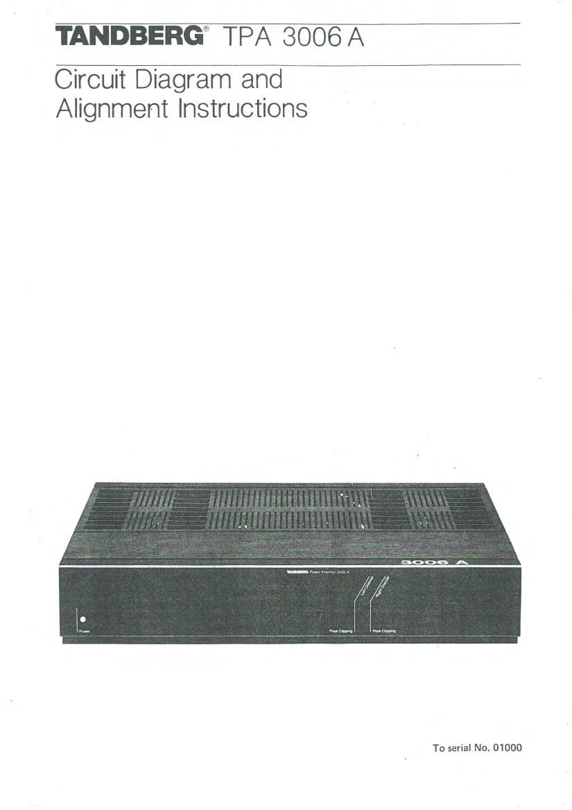
Tandberg TPA 3006 A Schematic

This is the 7 pages manual for Tandberg TPA 3006 A Schematic.
Read or download the pdf for free. If you want to contribute, please mail your pdfs to info@audioservicemanuals.com.

Page: 1 / 7
left right
Tandberg TPA 3006 A Schematic

Extracted text from Tandberg TPA 3006 A Schematic (Ocr-read)


Page 1

TANDBEI:!G® TPA 3006A

Circuit Diagram and
Alignment instructions

To serial No. 01000

Page 2

Dismantling

0 Top cover, rear (1)
0 Top cover, front (2)
0 Rear panel (3)

0 Front panel (4)

0 Bottom cover (5)

Dismantling the rear and top covers.

Dismantling the front and bottom covers.

Adjustments
Test condition

Approx. 10 minutes warming up time without
signal applied, The top and bottom cover should
not be removed, otherwise the unit must be
covered.

D.c. offset adjustment

- Solder two LEDs (light emitting diodes)
with opposite polarity together in parallel and
connect them to the contacts J106 (left) and
J206 (right) on the power amplifier boards
(collectors on 01 11/0112 left and 0211/0212
right .

- Adjust R104 (left) and R204(right) until both
LEDs are switched off.

- Remove the LED's and measure the dc.
voltage on the output terminals. The d.c
voltage should be less than t 50 mV.

Quiescent current

The quiescent current should be adjusted without
load and the volume control must be set to
minimum.

- Adjust R171 (left) and R271 (right) on the
output amplifier boards to 35 mV across
R505 (left) and R605 (right) on the power
supply board.

Distortion

Apply a signal of 1 kHz and drive the amplifier
to 12 V on the output terminals when the load
is 4 ohms.

- Adjust R163 (left) and R263 (right) to
minimum distortion. The distortion should be
less than 0.005%.