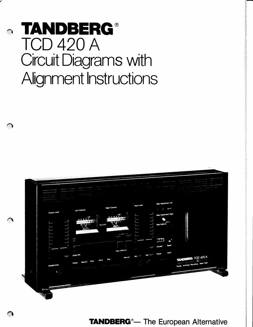
Tandberg TCD 420 A Service Manual 2

This is the 16 pages manual for Tandberg TCD 420 A Service Manual 2.
Read or download the pdf for free. If you want to contribute, please mail your pdfs to info@audioservicemanuals.com.

Page: 1 / 16
left right
Tandberg TCD 420 A Service Manual 2

Extracted text from Tandberg TCD 420 A Service Manual 2 (Ocr-read)


Page 1

Electrical checks and adjustments General - 0 dB level is defined as: 0.775 V in the RADIO socket, using Ty'pe I or II tapes. 1.2 V in the RADIO socket using Metal tape. 1.5 V in the OUTPUT sockets using Type I or II tapes. 2.3 V in the OUTPUT sockets using Metal tape. - Before adjusting, the tape path must be cleaned and demagnetized. It is necessary that the tape path is correctly adjusted. - Carry out the adjustments in the order described because the adjustments affect each other. - Remove the base panel. - When adjusting the Bias-traps and the Bias-pre- adjustment, the top panel must be removed. Equipment required - 2 millivoltmeters - Audio signal generator - Frequency counter - Distortion meter - Wow and flutter meter - Tandberg test cassettes: - No. 21 (Speed check, 1000 Hz) - No. 22 (Wow and flutter check, 3150 Hz) - No. 23 (Azimuth adj. playb. head, 6300 Hz) - No. 24 (Playback level adj., 1000 Hz) - Measuring cassettes: - Maxell UD XL I (Type I) - Maxell UD XL II (Type II) - Fuji Metal or TDK Metal MA (Metal) Before adjusting, set buttons to: - MPX-FILTER (situated at the back of the deck) to OFF. - Dolby NR.* to Off. - Output Lcvel controls * The words "Dolby" is registrered trade marh of Dolby Laboratories Inc., US. Nfi stands for Noise Reduction. Before adjusting, fold out page 5. Oscillator The oscillator frequency is between 80 and 100 kHz. The voltage measured on the erase head should be between 6 and 8 volts with Type II or Metal cassettes. Bias traps - Remove the top panel. - Nleasure with a millivoltmeter on C107 and C207 and adjust L101 and L201 to minimum reading on the millivoltmeter. Record/Playback head - azimuth - Insert a Tandberg test cassette No. 23 or a standard azimuth cassette. - Set the Monitor button to Taoe and connect a millivoltmeter to each channel of the OTITPUT sockets. - Press the Play button. Adjust the playback azimuth screw shown in the figure to obtain maximum reading on each channel. to maximum. Playback level - Insert Tandberg test cassette No. 24 (Playback level adjustment 1000 Hz). - Adjust with the PLAYBACK LEVEL ADJ. R317/R417 to 1.5 V on the OUTPUT sockets. (In the RADIO socket, adjust to 775 mV.) - If you use a Dolby level cassette, adjust to 1.2 V on the OUTPUT sockets (0.615 mV in the RADIO socket). Bias (pre-adjustment) - Set the TCD 420A to record, Metal tape loaded. - Adjust with R21031IJ.2203 (Bias Adjustment Metal) to approximately 8 - 9 mV measured on TPl and TP2 (on the Osc. board), see figure.

Page 2

NOTE! Adjusting the TCD 420A, using the RADlo-socket. Overall frequency response with Metal tape Set theTCD 420A to recording. Adjust the gene- rator to - 30 dB (= 25 mV on the millivoltmeters) and record a40OHz, a 10 kHz, and a 15 kHz signal at this level. - Rewind and play back. - Use the 400 Hz signal as a reference and check on both channels that the 10 kHz and 15 kHz signals are within the following tolerance: r3dB. If outside the tolerance adjust R2103/R2203 BIAS |DJ. M!,TAL. Then make a new recording, play back and check once more. - If you can not adjust to correct response with \?1991R2203, BIAS ADJ. METAL, then adjust R501/R601, TREBLE ADJ. METAL. - Make a new recording, play back and check once more. - Then check the frequency response t 3 dB, 30 - 18000 Hz. - When the frequency response is correct, check the response with the Dolby NR. circuit "On". Recording Level - Metal tape Connect an audio-generator and two millivoltmeters to the RADIO-socket. Set the TCD 420A to Record, use Metal tape. Adjust the generator to 400 Hz (= 450 mV on the millivoltmeters). - Start recording. - Rewind and play back (Output Level controls to maximum). - The millivoltmeters should now read approxi- mately 450 mV (- 2 to 0 dB). If outside the tolerance, make a new recording while adjusting R105/R205, REC. LEVEL METAL as required. Then play back and check once more. Distortion - Metal tape - Set the TCD 420A to recording. - Generator to 1000 Hz (= 775 mV on the milli- voltmeters). - Rewind and play back. - Check that the distortion is ( 3%. - If outside the tolerance, adjust R2103/R2203, BIAS ADJ. METAL. - Make a new recording, play back and check once more. - Then check that the frequency response is within the tolerance. Signal/noise - Metal tape The signal/noise ratios at 3To distortion should be at least as good as specified. Measure with the Dolby NR. circuit "On". IEC A-curve 68 dB IEC Linear RMS 56 dB Program meters - Metal tape - Set the TCD 420A to Record. - Record a 400 Hz signal from the generator (=11.2 V on the millivoltmeters) and adjust the program meters to 0 dB deflection on the Metal ry3l9 _11th Rl35/R235, METER LEVEL ADJ. RECORD. ^