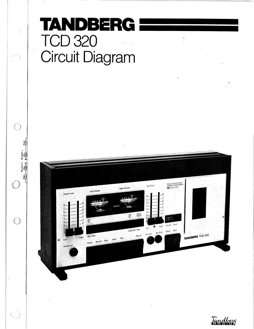
Tandberg TCD 320 Service Manual

This is the 4 pages manual for Tandberg TCD 320 Service Manual.
Read or download the pdf for free. If you want to contribute, please mail your pdfs to info@audioservicemanuals.com.

Page: 1 / 4
left right
Tandberg TCD 320 Service Manual

Extracted text from Tandberg TCD 320 Service Manual (Ocr-read)


Page 2

Osc.Board

Dolby Board

ELECTRICAL CHECKS AND '>
ADJUSTMENTS FOR '
TCD 320

Dolby honrdr ;

W- csm

C501 C603 90
A mplr'firr 2 board Q 3506 @
R135 N105 R205 R235

tau/Q bung
A mphfit-r I board

azmum


Location of test points and adjustable components

General Necessary equipment
- 0 dB" level is defined as 775 mV. Thus - 5 dB - 2 high impedance voltmeter: (do NOT use

equals 450 mV and - 40 dB equals 7.7 mV. universal meters).

- F .

- Make the adjustments in the order in which they 1 mum"

are listed here. Many of the adjustments require _ Audio Ecnflawr-

that previous adjustmens have already been - Distortion meter.

correctly madC- It is esredallv important that 7 Wow meter (required for wow test only).

adjustment for Maxell UD XL II tape (Tape S _ . .

button depressed) to be made before adjustment 7 peclal "015': measuring mm" (5" tables? 35)

for Maxell UD XL I tape (Tape button released). - Tandbcrg test tapes No. 21 (1000 Hz speed test),

No. 22 (3150 H2. wow test), No. 23 (6300 Hz

- Clean and degauss the tape path before and after azimuth test), and No. 24 (1000 Hz playback

the adjustments. It is assumed that the tape path 1¢V61)-

has already been correctly adjusted as described _ Maxell 1m XL 11 or equivalent.

in the Service Manual for the TCD 310 .

(ordering No. 715105). 7 Maxell UD XL 1 or equivalent.

Adjustment Set the cassette Measuring Measure Correct
No. or check Tape deck to instrument at reading Adjust Comments
1 Record/playback No. 23 Playback Voltmeters OUTPUT Maximum output Azimuth screw Adjust to best compromise.
head azimuth sockets signal. Difference on head
between the tracks:
< 5 dB

2 Playback level No. 24 Playback Voltmctcrs OUTPUT 775 mV R317 left channel)

sockets R417 right channel)

3 Tape spccd No. 21 Playback Frequency OUTPUT : 1%
counter socket (990 » 1010)

4 Wow No. 22 Playback Wow meter OUTPUT < 0.15% Measure at cud of ta c. Measure
(according socket (DIN 45511 both in vertical and orizontal
to eak weighted) position.

DIN 45507 _ ccord/p ayback:
< 0.2%
5 Oscillator Maxell Tape - Type II Frequency Connect 80 - 100 kHz Connection is made with a coil
frequency UD x1. ll Recording counter inductively or a few turns of ordinary wire.
to erase Instead of a frequency counter
head (see a long-wave receiver (tuned to
comments) 3rd. harmonic) can be used,
6 Oscillator Maxell Tape - Type II Voltmcter Across 28 - 32 V
erase voltage UD XL 11 Recording erase head
7 Oscillator 6?)ng [1 Tape - Type II Voltmctcrs OUTPUT < 2 mV INPUT sockets open.