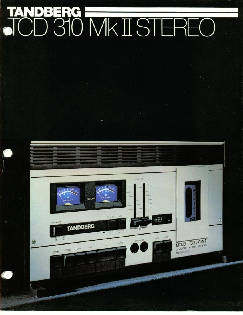
Tandberg TCD 310 Mk2 Stereo Service Manual

This is the 2 pages manual for Tandberg TCD 310 Mk2 Stereo Service Manual.
Read or download the pdf for free. If you want to contribute, please mail your pdfs to info@audioservicemanuals.com.

Page: 1 / 2
left right
Tandberg TCD 310 Mk2 Stereo Service Manual

Extracted text from Tandberg TCD 310 Mk2 Stereo Service Manual (Ocr-read)


Page 2

TCD 310 MkIISl -

EO

-3 motors, dual-capstan closed-loop tape drive
system, Dolby B nelse FGdUCthll system

TheTCDSlOMkHls-newmodellnthe
series of cassette tape decks from Tand-
berg. It was developed from the Model
TCD 310 which has been test-reported in
Iii-Fl magazines to many countries. The
tests have placeed the TCD 310 among
the best cassette tape docks in the world.

0 Frequency range: 30 Hz to 16000 Hz
(DIN 45 500)!

a Tape transport system has 2 who:
and 2 pressure rollers (closed loop).
Amongst other things means that speed
variations are reduced to a very low
levd

0 Electronic control

a Tandherg-developed input clrcults,
optimized for minimum nolse regard-
less of source in

0 High quality magnetic heads

a Large peak level meters

0 Mixing in mono

0 Automatic stop

a Jack output for stereo headphones

e Built-In multlpler-filter for recording
FM stereo programmes

0 Can he used in vertical position

e For use with separate ill-Fl stereo
amplifier

The tape transport

The dual-capstan closed-loop system
consists of 2 capstans with precision fly-
wheels and 2 pinch rollers. This provides
a stable tape path with minimum speed
variations. The mechanism is simple and
solid giving a reliable performance.
Even heavily worn cassettes will not be
damaged in the TCD 310 Mk ll because
it has a built-in safety device that auto-
matically stops the tape-drive if the tape
is jammed.

3 motors

The TCD 310 Mk II has one synchronous
motor for record/ replay and two motors
for fast forward and backward winding.
These two motors are in direct contact
with the spool spindles. This ensures that
the number of moving parts is reduced to
a minimum, and there is no complicated
mechanical transmission that could even-
tually wear and reduce the performance
of the machine.

Prlnted in Norway. 1276

Sell-adjusting Input amplifier

This novel self-adjusting input amplifier
was specially designed at Tandbergs
Radiofabrikk. While conventional input
amplifiers are optimized to a particular
program source and are often badly
matched to other program sources,

this amplifier adjusts itself automatically
to different program sources (radio.
record player with ceramic pick-up.
amplifier. microphone). The result is
something that cannot be achieved with
conventional amplifiers: a full dynamic
range and the absolute minimum noise
from the input circuits - regardless of
which program source and which
recording level are used.

Why the TCD 310 Ml: II has peak meters
A VU meter only indicates the average
value of the sound level which is some
where between the weakest level and

the strongest level during a given time
interval. This type of meter will

not reveal the peak intensity of short.
powerful sound impulses and therein lies
its disadvantage - exactly where there is
the biggest danger of distortion. In
practice it is impossible to avoid overload-
ing a tape now and then on a tape
recorder equipped with this type of level
meter. Tandberg tape recorders have
always been equipped with
peak-indicating meters because we believe
they give the truest indication of the
sound level. On all Tandberg tape
recorders the level meters are connected
after the frequency-corrected record
amplifier. For this reason the meters
measure direct the current flowing in the
record head. Tandberg is one of the very
few manufacturers in the world who
connect peak-indicating meters in this
way! Peak-indicating meters always show
the most powerful components in the
sound signal regardless ofthcfrequcncy
of the sound.

Correct use of the large. precise peak
meters on the TCD 310 Mk 11 results in:
correct indication of the level at all times.
never any audible distortion. and full
exploitation of all the characteristics of
the tape!

The Dolby B system

The TCD 310 Mk II has the Dolby noise
reduction system. This reduces tape noise
by about 10 dB compared with conven-
tional systems. The Dolby system is
especially important in a cassette tape
recorder because the tape noise is higher
than in a reel-to-reel tape recorder. The
Dolby system can be connected and dis-
connected with a switch.

Multiplex filter can be switched

in and out

All FM stereo transmissions have a pilot
tone that needs to be attenuated by a
filter before the program is recorded. In
tape recorders using the Dolby system
(such as the TCD 310 Mk II) it is
essential to have a filter because the
Dolby circuits accept the pilot tone as a
program signal. If the filter is not present.
the recording will have the wrong
frequency curve and the reproduction will
not be true.

General

DIMIIBM: width 17' (43 cm). height "I." (10.5 Cm)
and depth 9] (23 Cm)
Weld: 14/. lb (6.0 kg).

Technical specification

Po-ov laminar-Ira: 240 V. 50 Hz 07115 V, on NI
mar mutation: 34 watts.
Tape speed: W." (4.75 cm) per second.
Speed tolerances: 11% maximum with nomlnal power
voltage and normal operating temperature.

sud-II: maximum 02% accoldlnp to
DIN 5511, peak. weighted.
Frequency w: (Kl H1 to moon Hz (DIN 45500. the
MPX tiller disconnected).
signal/tape noise ratio, measured wlln Tamper: Tape or
equal lane. Dolby circuits connected. Relevance 3%,
3m harmonic distortion: greater than 65 dB (lEC A sum
and am 45500, Guiuschspannung)
Greater than 55 dB (IEO, near HMS and DIN 45 500.
mespannung).
amt-l saturation at 1000 Hz: pleatsrthan so :15 lmm
side 1 to side 2 and greater than 35 dB trom trick l to
track 2
Harmonie flotation: less than 0.3% lrom the amplifier
with 0 GB (DC. IMI: less than 3% lvom the tape will! 0 GE
rec. Iml.
Inputs: MIC: the Input Impedance adjusts use" auto-
matically to dynamlc microphones with an Impedance
between 100 and son ohms. Sensitivlty "cm 0.15 mV to
20 my. LINE: input impedance 220 k ohms. sensitivity
lrom 40 mV to 5 V. RADIO; Input impedance 47 k ohms.
Sensitivity lrom 8 mV to l V.
Outputs: RADIO/LINE: output impedance 10 k ohms.
Voltage level 0.775 V. HEADPHONES: minimum load
importation 3 ohms. Output power 2 mW at 8 ohms.

' The name Dolby lsa registered trade mark ol Dolby
Laboratories Inc, USA.