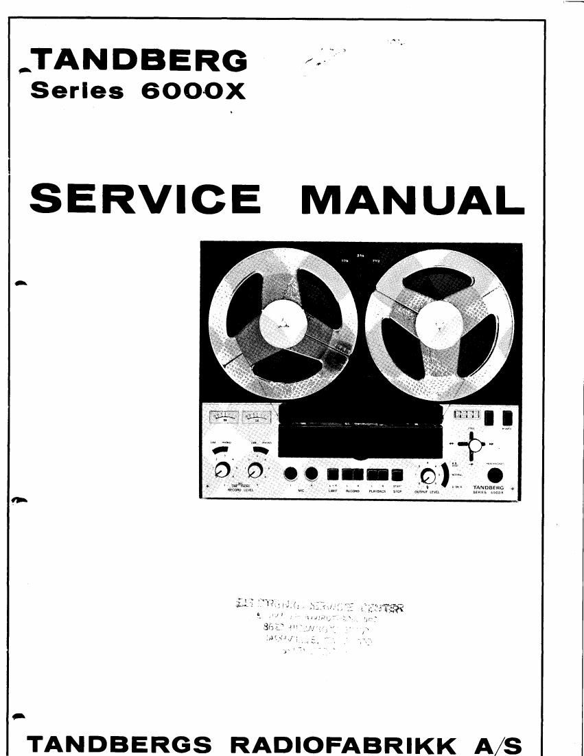
Tandberg 6000 X Service Manual

This is the 30 pages manual for Tandberg 6000 X Service Manual.
Read or download the pdf for free. If you want to contribute, please mail your pdfs to info@audioservicemanuals.com.

Page: 1 / 30
left right
Tandberg 6000 X Service Manual

Extracted text from Tandberg 6000 X Service Manual (Ocr-read)


Page 1

-\ t'>, CONTENTS 1.0 Mechanical Adjustments 1.1 Clutches1.1.1 Take-up T rntable 1.1.2 Supply T rntable 1.2 Brakes 1.3 Pressure Pad Adjustment 1.4 End Stop Mechanism 1.4.1 Tape Feeler Tension 1.4.2 Adjustment of Tape Feeler Alignment2.1 Demagnetizing 2.2 Bias- and Erase Circuits 2.2.1 Oscillator Frequency 2.2.2 Erase Voltage 2.2.3 Bias Current Tape Path 3.1 Visual Check 3.2 Mechanical Adjustment of Tape Path Head Alignment with Tandberg Test Tapes Model 6041X 4.1 Playback Head 4.1.1 Height Adjustment 4.1.2 Azimuth Adjustment 4.2 Record Head 4.2.1 Height Adjustment by Visual Inspection 4.2.2 Height Adjustment by Track Measurement 4.3 Bias Head 4.3.1 Vertical Adjustment 4.3.2 Height Adjustment 4.3.3 Horizontal Adjustment 4.4 Erase Head 4.4.1 Height Adjustment 4.4.2 Azimuth Adjustment 4.5 Model6021X Head Alignment Without Tandberg Test Tapes, Model 6041X 5.1 Playback Head 5.1.1 Height Alignment 5.1.2 Azimuth Alignment 5.2 Record Head 5.3 Bias Head 5.4 Erase Head 5.4.1 Height Adjustment 5.4.2 Azimuth Adjustment 5.5 Model 6021X 7.0 Adjustment and Control of the Amplifiers 9 7.1.1 Playback Level Adjustment I 7.1.2 Adjustment of Bias Current 9 7.1.3 Record Level Adjustment 9 7.1.4 Record/Playback Curves I 7.1.5 Indicator Adjustment in Record Mode 9 7.1.6 Distortion I 7.1.7 Indicator Adjustment in Playback and Amplifier Modes 9 7.1.8 Control of the Playback Amplifier I 7.2 Tape Speed Control 10 7.2.1 Using Frequency Meter or Counter 10 7.2.2 Using Transformer and Vacuum Ttrbe Voltmeter 7.2.3 Using Tape of Known Length 8.0 Adjustment of the Amplifiers, without Tandberg Test Tapes 8.1 Playback and Record Level Adjustment 8.2 Record/Playback Curves 8.3 Readjustment of Record Levels and Indicators 10 8.4 Distortion 10 8.5 Control of Playback and Record Amplifiers 11 8.5.1 Playback Amplifier 11 8.5.2 Record Amplifier 11 8.6 Pick-up Amplifier Curve 11 8.7 Limiter 12 8.7.1 Adjustment of Limiting Threshold 72 8.7.2 Adjustment of Release Time 12 9.0 Modifications 9.1 Modification from 230/115V 50 Hz to 230/115V 60 Hz operation 9.2 Modification from Four-Track to Two-Track Venion 9.3 Important Electrical Modifications Introduced in Series 6000X 10.0 Lubrication 11.0 Illustrations with Reference Part Numbers 12.0 Spare Parts List for Tandberg Tape Recorder 6000X 12.1 Mechanical Parts 12.2 Screws, Washers, Nuts and Circlips 12.3 Electrical Components 12.3.1 Transistors 12.3.2 Diodes 12.3.3 Rectifier 1 2.3.4 Trimming Capacitor 12.3.5 Poientiometers 12.3.6 Heads 12.3.7 Transfonners 13.0 Transistor and Diode Identification 14.0 Block Diagram Series 6000X 15.0 Printed Wiring Boards and lViring Diagram 2.0 3.0 4.0 I I I tt I 1010 10 1010 t2 13 5.0 13 13I4 1.7 772L 21 2L22229',t 2222 23 23 24 6.0 Track Control 6.1 Model 6041X 6.1.1 Record Head 6.1.2 Erase Head 6.1.3 Playback Head 6.2 Model 6021X 6.2.1 Erase Head 6.2.2 Record Head 6.2.3 Playback tlead ^

Page 2

1.0 1.1 MECHANICAL ADJUSTMENT Clutches 1.1.1 Take-up Turntable Normal Forward drive Set the operating lever to normal forward drive position with the motor running. Ensure that the clearance between the polyurethane friction pads under the turn- table and friction disc 991009 lays between 0,5-0,9 mm (0.02"-0.035"). If necessary, adjust screw A as shown in fig. 1.1. 1 991 034 0,5-0.9 mm L {0.02"-0.35") I - Control of Winding Torque Note: All controls and measurements must be carried out with the tape recorder placed in horizontal posi- tion and with empty reels only. The control is accomplished as shown in fig. 1.2, which presents two optional modes of control. Fig. 1.2 Control of winding force. Normal forward drive mode. Fast Forward Winding Control of Fast Winding Torque Set the operating lever to fast forward winding position. The control is accomplished as shown in fig. 1.3, which presents two optional modes of control, - il 991017 991013 Fig.1.1 .rl 30 mm radius Force:4O-80g 80 mm radius While measuring, the reel should be allowed to have a slow rotation. The instrument should follow the movement in a straight line towards the tape recor- der. Notc: After a longer period of continuous operation, an increase of the torque by 20-30V" is considered as normal. Force:15-30g .arl 4 +i I