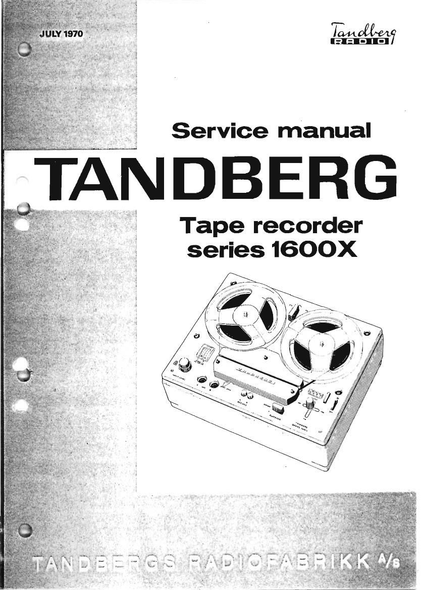
Tandberg 1600 X Service Manual

This is the 50 pages manual for Tandberg 1600 X Service Manual.
Read or download the pdf for free. If you want to contribute, please mail your pdfs to info@audioservicemanuals.com.

Page: 1 / 50
left right
Tandberg 1600 X Service Manual

Extracted text from Tandberg 1600 X Service Manual (Ocr-read)


Page 1

imam
[5121313]

Service manual

NDBERG

Tape recorder
series 1600X

Page 2

CONTENTS

1.0 Technical Specifications ........................ 2

2.0 Operating Contmls ............................. 4

3. 6 input and Output Terminals ...................... 5
4. 0 Tnpe Transport Mechanism. Detailed Descrip-

tion and Alignment Prosedures .................. 6

4.1 Operating Lever 990225 ................... 6

4.1.1 Eccentric Segment 990203 ......... 1. .. 7

4.1.2 Pressure Roller Arm 990302 .......... 7

4.1.3 Operating Arm 248186 ................ 8

4.2 Turntables ............. ... 10

4.2.1 Supply Turntable 10

4.2.2 Tape Tension ..... 10

4.2.3 Take-up Turntable ................... 11

4.2.4 Adjustment of Turntables ............. 12

4.3 Clutches .................................. 13

4. 3. 1 Neutral ............................. 13

4.3.2 Normal Forward Drive ............... 14

4.3.3 Fast Forward Winding ................ 15

4.3.4 Fast Reverse Winding ................ 15

4.3.5 Free ........... 16

4.4 Motor Pulley 2439400 . 17

4.5 Drive Belt 213997 .......................... 17

4.6 Transfer Wheel 990233 ..................... 18

4. 7 Lifting Arm 990201 ......................... 18

.8 Flywheel with Capstan 990312 ............... 19

.9 Speed Selector ............................. 20

5.0

.11 Pressure Pad.
.12 End Stop Mechanism
4.12.1 Neutral ........

4
4
4.10 instantaneous Start/Stop Mechanism. . .
4
.1

4.12.2 Normal Forward Drive .............. 22
4.12.3 Free .............................. 22
4.12.4 End Stop or Tape Breakage .......... 23
4.12.5 Tape Feeler Tension ................ 23
Electronic Circuits. Detailed Description ........ 24
5.1 The Main Electronic Units. Block Diagram... 24
5.1.2 Microphone and Line Amplifier . 25
5. 1.3 Butter Amplitier.. . 25
5.1.4 Record Equalizing Amplifier .......... 25
5.1.5 Indicator Amplifier .................. 26
5.1.6 Oscillator with Amplifier.
Bias- ,and Erase Circuits ............ 27
5.2 Playback Electronics ...................... 27
5. 2.1 Playback Equalizing Amplifier ......... 27
5.2. 2 Playback Booster Amplifier ........... 28
5.3 Power Supply.- ............................. 29
5.4 Output Switching System .................... 29
5.4.1 Playback Selector with Output
Receptacles ......................... 29

Alignment of Electrical Circuits and Tape Path. . .. 30

6.1 Head Alignment and Track Control with
Tandbe rg Test Tapes ....................... 30

6.1.1 Model 1641K (Four Track).
6.1.2 Demagnetizing ..............

6.1.3 Tape Guide Adjustment ............... 30
6.1.4 Record/Playback Iiead ................ 30
6.1.5 Height Adjustment .................... 30
6.1.6 Azimuth Adjustment .................. 30
6.1.7 Control of Playback Curves ............ 30
6.1.8 Erase llead ...................... . 30
G. 1. 9 Height Adjustment... . 30
6.2 Model 1621X (Two Track).. . 30

6.3 Head Alignment without Tandberg Test Tapes.. 30


6.3.1 Demagnetizing ....................... 30
6.3. 2 Record/Playback Head ................ 30
6.3.3 lleight Alignment ...................... 30
6.3.4 Lateral Alignment .................... 31
6.3.5 Azimuth Alignment .................... 31
6.3.6 Erase Head .......... ....... 31
6.3.7 Height Alignment. . 31
6.3. 8 Lateral Alignment. 31
6.3.9 Azimuth Aliyirnent .............. 31
6.4 Track Control, Model 1641X-Four Track,
without Tandberg Test Tape. . . . 31
6.4.1 Record/Playback Head . 31

6.4.2 Erase Head .................
6.5 Track Control, Model 1621X- Two Track,
without Tandberg Test Tapes. . . ... 31
6.5.1 Erase Head ................. 31
6.5.2 Record/Playback Head ................ 32
6.6 Electrical Adjustments for Taudberg
Tape Recorder Model 1641K and 1621X ....... 32
6.6.1 Adjustment of Output Level ............ 32
6. 6. 2 Adjustment of Oscillator Frequency
and Bias ............................ 32
6. 6.3 Using Frequency Meter (Counter) ..... 32
6.6.4 Using Signal Generator and Radio
Receiver .......................... 32
6.6.5 Control of Erase Voltage .............. 32
6.6.6 Adjustment of Bias ................... 32
6.6.7 Preadjustment oi Recording Level
and Indicator ........................ 32
6.6.8 Adjustment of Bias Head ............. 32

6.6. 9 Control of Total Frequency Response... 33

6.6.10 Adjustment of Record Level and

indicator applying Test Tape .......... 33
6 6.11 Distortion .......................... 33
6.6.12 Tape Speed Control .................. 33
6.6.13 Control of Playback Curves .......... 33
6.6.14 Control of Recording Curves .......... 33

6. 7 Modifications from Four Track to Two Track

Version ................................... 34

6.8 Connections and Modifications [mm 11am»
230-240\ and from 50 to 60 Hz (or 60 to 50 Hz)

Operation .................................. 34

7.0 Spare Parts List ............................... 35
Mechanical Parts .............................. 35
Electrical Components. . . 39
Lubrication Notes. . . 45
Set of Special Tools ....... 45
Circuit Diagrammes and Printed Boards ............. 46