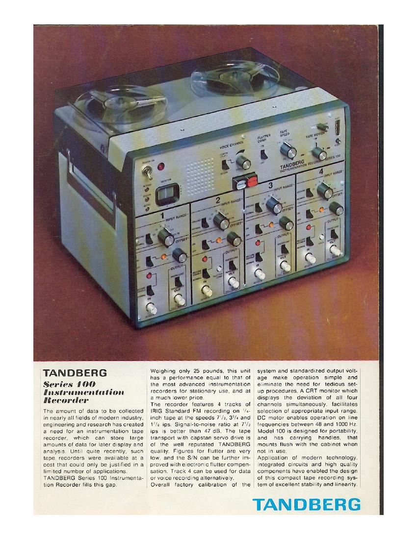
Tandberg 100 Brochure

This is the 5 pages manual for Tandberg 100 Brochure.
Read or download the pdf for free. If you want to contribute, please mail your pdfs to info@audioservicemanuals.com.

Page: 1 / 5
left right
Tandberg 100 Brochure

Extracted text from Tandberg 100 Brochure (Ocr-read)


Page 1

.TANDBERG
rips 100

"(err)! r

The amount of data to be collected
in nearly all fields of modern industry.
engineering and research has created
a need for an instrumentation tape
recorder. which can store large
amounts of dala for later display and
analysis. Until quite recently. such
tape recorders were available at a
cost that could only be justified in a
limited number of applications.
TANDBERG Series 100 Instrumenta-
tion Recorder fills this gap.

Weighing only 25 pounds. this unit
has a performance equal to that of
the most advanced instrumentation
recorders for stationary use. and at
a much lower price.

The recorder features 4 tracks of
IRIG Standard FM recording on /i-
inch tape at the speeds 7V7. 3% and
1/a ips. Signal-to-noise ratio at 7/2
ips is better lhan 47 dB. The tape
transport with capstan servo drive is
of the well reputated TANDBERG
quality. Figures for flutter are very
low. and the S/N can be further im-
proved with electronic llutter compen-
sation. Track 4 can be used for data
or veice recording alternatively.
Overall factory calibration of the

system and standardized output volt-
age make operation simple and
eliminate the need for tedious set-
up procedures, A CRT monitor which
displays the deviation of all four
channels simultaneously, facilitates
selection of appropriate input range
DC motor enables operation on line .
frequencies between 48 and 1000 Hz.
Model 100 is designed for portability.
and has carrying handles. that
mounts flush with the cabinet when
not in use. .
Application of modern technology.
integrated Circuits and high quality
components have enabled the design
of this compact tape recording sys-
tem of excellent stability and linearity.

TANDBERG

Page 2

FEATURES

RECORDING

ERASURE

INPUT OFFSET

CAPSTAN
SPEED CONTROL

VOICE AND
DATA CHANNEL

FLUTTER

COMPENSATION

DATA CHANNELS

SIGNAL MONITOR

COPYING

TANDBERG

Button interlocked with tape motion lever prepares all channels lor record mode
at operation.

Separate record able/disable switches lor each channel allow recording on one or
more tracks as desired. Pilot lamps indicate channel not in use.

Separate lull-track erasure obtained by simultaneously depressing buttons ERASE
and RECORD. Remanent signal on the tape alter erasing is more than 70dB
below normal recording level. Recording can occur simultaneously.

A separate degausser is therefore not needed.

An uncalibrated ollset control can be activated by OFFSET switch on each chan-
nel. A DC voltage twice the selected input range can then be balanced out,

The tape speed is sensed by a tachometer on the capstan shall and compared
against a lixed relerence. The error voltage is amplilied and applied to the motor
to alter the motor torque as required to maintain constant tape speed.

Channel 4 has three modes at operation: Data only. voice-only and data inter-
rupted by voice. When voice IS recorded. the carrier is given a constant + 60%
deviation which serves as an indication ol voice recording. In reproduce mode.
data is normally led to the output terminal. When voice (60 °/o deviation) is de~
tested. the data output is automatically grounded and voice is reproduced through
speaker or headphones.

Channel 2 can be used tor llutter compensation or data. When recording in llutter
compensation mode. the data input is grounded. and the recorded carrier is mo-
dulated by flutter. In playback. output lrom the llutter channel is subtracted lrom
the signal in the data channels. giving an improved signal-to-noise ratio at the
data output.

The overall gain ol the FM record/reproduce system can be selected with the
Input attenuator, allowing lull deviation tor signals between : 0.5 and ;: 20V.

The CRT monitor is permanently connected to the output at the reproduce elec-
tronics. The output signal is t 5 volts tor lull deviation.

All four data reproduce output voltages are sampled sequencially and displayed
on a switched beam CRT. This monitor aids the selection oi correct INPUT RANGE.
Because the system is calibrated. the attenuator setting alone determines the
relationship between input and output voltages.

Inputs and outputs lor copying or transmission at modulated carrier lrom one tape
recorder to another, are provided on the rear panel.