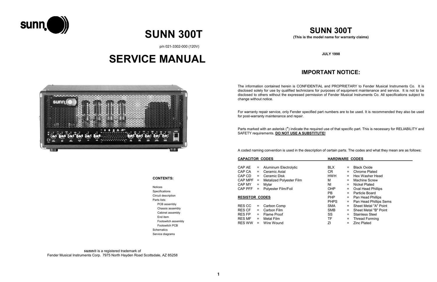
Sunn 300t service manual

This is the 14 pages manual for sunn 300t service manual.
Read or download the pdf for free. If you want to contribute, please mail your pdfs to info@audioservicemanuals.com.

Page: 1 / 14
left right
sunn 300t service manual

Extracted text from sunn 300t service manual (Ocr-read)


Page 1

SPECIFICATIONS Product Release No.:PR 347 (This is not a model number) Part Number:120V Version : 21-3302 240V Aust : 21-3332 230V UK : 21-3342 230V : 21-3362 100V : 21-3372 Power Requirements:All Versions : 900W Preamp Section Input impedance:470 k-„¦ Full power sensitivity:12 mV Tone controls:Treble: +/- 15 dB @ 6kHz Bass: +/- 15 dB @ 40Hz Graphic equalizer:+/- 12 dB @ 31.5Hz, 63Hz, 125Hz, 250Hz, 500Hz, 1kHz, 2kHz, 4kHz, 8kHz, 16kHz Mid notch:-20 dB @ 700Hz Low boost:+10 dB @ 40Hz High boost:+10 dB @ 6kHz Compressor Crossover:400Hz Ratio:1:1 min to 4:1 max Line out level:+6 dB referenced to input (pre), 0 dBV (post) (Transformer balanced) Power amplifier section Input impedance:20 k-„¦ Power output:300 W atts RMS into 2, 4, 0r 8-„¦ @ <3% THD Sensitivity:1V RMS (0dBV) Speaker Complement:Designed for use with the Sunn 410H or Sunn 215 Bass Loudspeaker Enclosures Dimensions:Height: 10.1" (25.7 cm) W idth: 25.5" (64.8 cm) Depth: 15.6" (40 cm) Weight:75 lbs. (34 kg) Product specifications are subject to change without notice CIRCUIT DESCRIPTION Preamp The preamp section employs two 12AX7 tubes. Channel one (V1) is fairly conventional, while channel two (V2) uses a second tube with additional op-amp gain (U2B) to provide a 60's style overdrive sound. The op-amp is used as straight gain and is never allowed to become non-linear. In typical operation, the drive channel and the clean channel are presented to the channel 1/2 mix control (R17) so that a "blend" can be established. The channel select button (S9) on the front panel (or it's foot switch counterpart) selects between this channel mix or channel one only. This selection employs JFETS Q1-Q4. Signals are then presented to a second - order Sallen and Key filter set to F 0 of 36.6 Hz and a Q of 2.1. This filter provides about 6.5dB of boost at 41 Hz. The signal path is routed to U17B where low-boost (S3) , mid-notch (S2), and high-boost (S4) equalization switches can be used. These circuits are followed by conventional Baxendall low (R58) and high (R62) equalization. The Baxendall circuit output is then sent to a graphic equalizer which can be selected by the footswitch or graphic EQ button (S7) on the front panel. The far-right graphic EQ slider (R71) is a +/- 10dB trim for graphic EQ gain compensation. Next, the signal is presented to a second-order state-variable filter before being presented to the compressor circuit. Said filter is set to 420 Hz. At the compressor, low-frequency compression ratio (R100) and high-frequency compression ratio (R119) are adjustable to suit the user. Audio is presented to the "compressor EQ balance" (R102). The compressor EQ balance controls the mix ratios of the compressor outputs. A compressor gain trim (R80) is provided to compensate for the amount of amplification lost due to using the compressor. The compressor-gain trim control is able to compensate for a compressed signal of up to 10dB. The FETs Q5 and Q6 select between pre- and post-compressor via the front panel switch (S8) or footswitch. After passing through op-amp U9B and master-gain control R107, the signal is sent to output jack J2, effects-loop send. The signal input at J3, effects-loop return, goes to differential receiver U11A. Heater voltage (24VDC for 2 series-connected 12AX7s in the preamp) is derived from the 32VDC supply (+/- 16VDC).. Excess voltage is dropped across across paralleled ballast resistors, R354-R356, on the preamp PCB.2

Page 2

CIRCUIT DESCRIPTION (CONT) Output section On the top side of the chassis, at the rear of each pair (total = 3) of output tubes, is an LED and a fuse. The LED glows green when the associated pair of tubes is operating properly, and glows red if a tube failure has caused the related fuse to blow. If a fuse blows, replace it only with one of the same type and rating. NEVER use a fuse with a higher current rating, as this could damage the equipment and present a serious safety hazard. Next, replace the tubes in their respective locations, check and adjust the bias and balance. NOTE: it is normal for the LEDs to glow red when the amp is in standby mode. Output tube bias adjustment instructions 1. Turn on the 300T and let it warm up for at least two minutes with the STANDBY switch in the ON position. Make sure the amplifier is connected to a speaker or equivalent load. 2. Remove the bias controls cover box. 3. W ith a DVM set to it's most sensitive DC voltage scale, measure the voltage between the BIAS 100mV test points, and adjust the BIAS control for a reading of .1 VDC (100mVDC).. 4. Next, connect the DVM to the BALANCE 0V test points, and adjust the BALANCE control for a reading of 0 VDC. 5. Replace the bias controls cover box. NOTES: 1. For optimum sonic performance, set bias to 100 mVDC first, then set balance. 2. If the output tubes cannot be biased to at least 80 mVDC, replace the 6550C output tubes. 3. If the output tubes cannot be balanced, check the bias setting and/or replace the 6550C output tubes. 4. If the power tube trouble LEDs are glowing green, it does not indicate that the tubes are not worn or weak. Tube layout: PARTS LIST NOTE: SHADED ITEMS ARE FOR REFERENCE ONLY PRINTED CIRCUIT BOARD ASSEMBLY QTY PART # DESCRIPTION REFERENCE DESIGNATION 4 054360 CAP AE AX 22uF 450V 20% 105C C162 C166 C170 C176 2 054361 CAP AE AX 47uF 450V 20% 105C C156 C159 4 033606 CAP AE RDL .47uF 50V 20% C102 C126 C127 C130 2 054355 CAP AE RDL 1000uF 50V 20% 105C C174-175 8 028463 CAP AE RDL 10uF 50V 20% C41 C78 C81 C85 C88 C113 C178-179 1 028458 CAP AE RDL 1uF 50V 20% C82 4 028459 CAP AE RDL 2.2uF 50V 20% C27 C109 C112 C120 36 028467 CAP AE RDL 22uF 50V 20% C16 C19-20 C31 C33-34 C36 C38-39 C45 C48 C51 C54 C57 C61 C64 C67 C70 C73-74 C80 C84 C86 C103 C107-108 C111 C115 C117 C124 C128 C144 C145 C147 C149-150 3 054356 CAP AE RDL 330uF 450V 20% 105C C171-173 4 028460 CAP AE RDL 4.7uF 50V 20% C2 C11 C12 C26 1 038699 CAP CA 100pF 100V 5% C37 2 039265 CAP CA 2200pF 100V 5% C79 C110 7 039259 CAP CA 220pF 100V 5% C8 C40 C104-106 C114 C116 5 038873 CAP CA 22pF 100V 5% C6 C15 C42 C59 C83 1 039261 CAP CA 330pF 100V 5% C142 2 038701 CAP CA 470pF 50V 5% C77 C163 2 039256 CAP CA 68pF 100V 5% C118 C119 25 034788 CAP CD .1uF 50V 20% .15" cut C4-5 C89-100 C121 C140-141 C146 C148 C151-155 C169 3 025995 CAP CD 8200pF 1000V 20% LL C167-168 C177 1 027256 CAP MPF .0015uF 100V 10% C30 3 027260 CAP MPF .0039uF 100V 10% C123 C125 C129 2 027264 CAP MPF .01uF 100V 10% C32 C35 1 024823 CAP MPF .01uF 400V 10% C18 11 027267 CAP MPF .022uF 100V 10% C23-25 C55-56 C58 C60 C62-63 C75-76 2 024835 CAP MPF .022uF 630V 10% C160-161 9 027272 CAP MPF .047uF 63V 10% C9-10 C87 C131-133 C138-139 C143 1 027275 CAP MPF .068uF 100V 10% C22 1 027277 CAP MPF .082uF 100V 10% C14 8 027280 CAP MPF .15uF 63V 10% C28-29 C46-47 C49-50 C52-53 2 024853 CAP MPF .1uF 250V 10% C157-158 4 024854 CAP MPF .1uF 400V 10% C3 C7 C13 C17 6 027278 CAP MPF .1uF 63V 10% C1 C21 C101 C122 C134-135 1 027281 CAP MPF .22uF 63V 10% C1373