Studer A 710 Owners Manual

This is the 49 pages manual for Studer A 710 Owners Manual.
Read or download the pdf for free. If you want to contribute, please mail your pdfs to info@audioservicemanuals.com.

Page: 1 / 49
left right
Studer A 710 Owners Manual

Extracted text from Studer A 710 Owners Manual (Ocr-read)


Page 1

STU EOE?!

STUDER A710 Kassettenbandmaschine STUDER A710 Professionai Cassette Re-
(Zusatz zu Bedienungsanieitung B71DMKII) corder
(Supplement to operating instruction

B710 MKII)
In diesem Zusatz sind diejenigen Ab- The foHowing sections differ from the
schnitte aufgef'uhrt, weiche f'u'r die B710 MKII operating instructions or

A710 eine Erganzung bedingen oder nicht have to be added:
mehr zutreffen:

Magnetophone a cassettes STUDER A710
(Suppiément 5 1a mode d'empioi B710 MKII)

Ce supplement contient 1e: paragraphes
qui exigent des indications compié-
mentaires quant au modeie A710 ou qui
ne sont pius vaiabies:

5-w1m 111211;: m 1m 31

Seite Index page index Page Index
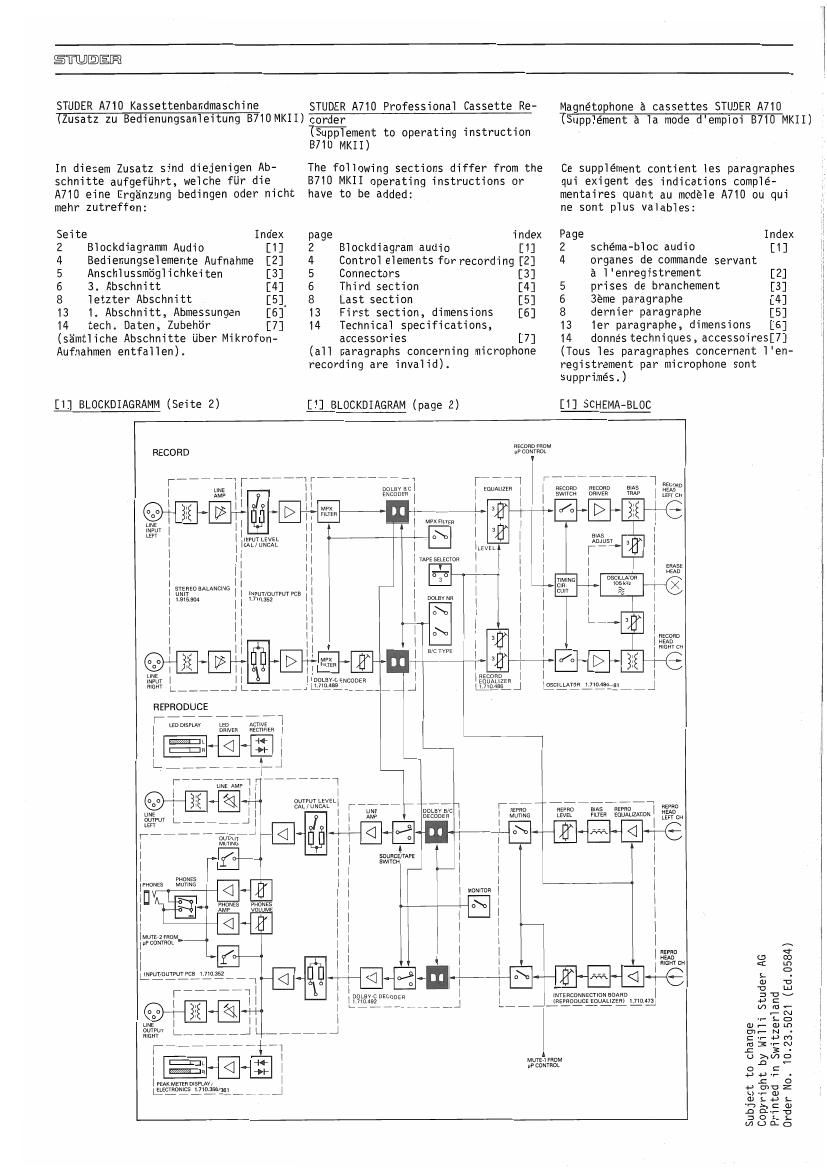
2 Biockdiagramm Audio [1] 2 Biockdiagram audio [1] 2 schema-bloc audio [1]
4 Bedienungseiemente Aufnahme [2] 4 Controi eiements for recording [2] 4 organes de commands servant
5 Anschiussmogiichkeiten [3] 5 Connectors [3] a I'enregistrement [2]
6 3. Abschnitt [4] 6 Third section [4] 5 prises de branchement [3]
8 ietzter Abschnitt [51 8 Last section [5] 6 3éme paragraphe [4]
13 1. Abschnitt. Abmessungen [6] 13 First section, dimensions [6] 8 dernier paragraphe [5]
14 tech. Daten, Zubeh'o'r [7] 14 Technicai specifications, 13 1er paragraphe, dimensions [6]
(s'a'mtiiche Abschnitte u'ber Mikrofon- accessories [7] 14 donnés techniques, accessoiresUJ
Aufnalnmen entfaiien). (aii paragraphs concerning microphone (Tous les paragraphes concernant I'en-
recording are invalid). registrement par microphone sont
supprimés.)
[1] BLDCKDIAGRAMM (Seite 2) [1] BLDCKDIAGRAM (page 2) [1] SCHEMA-BLOC
RECORD 3531:1211?
7, 71 77777 irii 777777 11777 77777 777 m
11.1; 1 1mm 1 mum 1 11;me can: Bus 3;

Excouzn 1

11-
111E111 E117'11
1NPUTLEVE1
1 uunm
1

1 1
1 1
1
1
1 1
1 1
1 WW 1
1 1 1
1
1 1
1 1
1 1

17 7 7777777 1

1 1
arklI7ll °WWM Vs
was 777 L,
1 1 1 r 1111; DOL v {3 115m

11 a
' 1
Emm L 1 1 chouEn 1 1 ~10in
1 a
7,, 7 .1-1-1 : WM 1
7 UM El 0
mm
1 1 1 1 1
1

suuncawz
swwcu

1

MVYE 1 ram » :12]-
1u1> coNWm -
flwnuuwuwca 171015

44L: 1
«11:1
1

am 0 g
1mm < m
a
L -
CD '0
'0 Lu
1mmmmmb zev
,_,L_,\, mm_
- N
0- L O
a) r- (I) m
m_NI
C '1- U r')
m3rN
.c 3 -
MUYEiFHOM U Est/7 2

WWW o C
1 2*5

Wmmw

a own 2

ficflumsflflfifli, J u _ G)
<1) L 44 L.
-1-, >, r: o
.0 our" '0
2 O L L
mono

nEcom
14m
1 mom (.11

was ems as Rim
mm mm momma» mm

Page 2

ESTTEJEDEEDQ

[1:11 C
_/© (D C
_ O O O O
[A] [C] [D]

[B]

PAUSE < > PLAY sme REC

FADER MONITOR
START

LI

l

1111
WHII'HJ'l

IS-POLE D We: coNNEcToR

1 51% R -.
E f. §L rum-150mm:
,0 .,, gig a "13ch
RELAY
ACTIVATED AT
> PROGRAMMED
9 START/STOP
' TIME

iii-nine:f-i-ii

[Z] Bedienungselementg (Seite 4)

Erwahnt werden nur die von der B710MKII

abweichenden Bedienungselemente.

[A] Eingangspegelregler
(bei gedrUckter Taste [8] aktiv)
[B] Aufnahmepegel-Umschalter
[C] Ausgangspegel-Umschalter
[D] Ausgangspegelregler
(bei gedru'ckter Taste [C] aktiv)

[2] Operating elements (page 4)
Those elements are mentioned only
which differ from B710 MKII:

[A]
[B]

[C]
[0]

Input level potentiometer (active

only if push button [B]is depressed)

Recording level switch
Output level switch
Output level potentiometer (active

only if push buttonEC] isdepressed)

[Z] Organes de commande (page 4)
Il n'est fait réfErence quaux elements
dievergeant de ceux du modele B710 MKII.

[A] Potentiometre pour le reglage du
niveau d'entree (actif lorsque la
touche [B] est pressée)
Commutateur pour le réglage du
niveau d'enregistrement
Commutateur pour le réglage du
niveau de sortie

Potentiometre pour le réglage du
niveau de sortie (actif lorsque
la touche [C] est pressée)

[B]
[C]
[D]

[3] Anschlussmoglichkeiten (Seite 5)

An der Geratefrontseite kann ein Kopf~
horerpaar angeschlossen werden.

An der Gerateru'ckseite befinden sich
Leitungsein- und Ausgange (XLR-Stecker)
und ein Fernstart-Anschluss.

[3] Connector field (page 5)

- Ear phone socket on the front plate

- XLR sockets for symmetrical line in-
put/line output on the back, as well
as the fader start socket.

[3] Prises de branchement (page 5)

Une paire d'ecouteurs peut etre branchee
sur le cote de front de l'appareil.

Sur le cote arriere de l'appareil se
trouvent les entrees et sorties de

ligne (prises XLR) ainsi qu'une prise
pour la mise en marche telecommandée.

[4] 3. Abschnitt (Seite 6)

- Bei gedr'u'ckter Taste [C] kann der
Ausgangspegel mit Regler [D] um
max. iOdB erhoht werden. Damit Fehl-
Aussteuerungen bei Aufnahme vermie-
den werden , kann nur bei Nieder-
gabe unkalibriert gewahlt werden
(siehe Serviceanleitung PCB 1.710.
352).

- Bei geloster Taste [C] ist der Aus-
gang auf Leitungspegel geschaltet.
Regler [D] ist wirkungslos.

[4] Third section (page 6)

- If push button [C] is depressed the
output level can be increased by max.
10dB with potentiometer [D]. To be
sure that the recording level cannot
be wrong, potentiometer [D] is only
active while the machine is not in
record mode. (see service manual PCB
1.710.352)

- If push button [Cc is released, the
output level is calibrated and the
potentiometer [D] is out of action.

[4] 3eme paragraphe (page 6)

- Lorsque la touche [C] est pressée,
niveau de sortie peut etre augmenté
au moyenne du potentiometre [D] de
ludB au maximum. Afin d'éviter de
fausses magnétisations pendent l'en-
registrement, le potentiométre [D]
n'est actif que lorsque la machine
se trouve hors enregistrement. (voir
instructions de service PCB 1.710.
352).

- Lorsque la touche [C] nest pas
pressée, le niveau de sortie corres-
pond au niveau de ligne. Le potentio-
metre [D] est alors sans effet.

le

[5] Letzter Abschnitt (Seite 8)

- Bei gedruckter Taste [B]: den Auf-
nahmepegel fUr beide Kanale auf OdB
(am PEAK READING METER) einstellen.

- Bei geloster Taste [8]: Eingangs-
pegel = Leitungspegel (Regler [A]
wirkungslos)

[fi] Last section (page 8)

- If push button [B] is depressed the
recording level for both channels
can be adjusted with potentiometer
[A] according to the PEAK READING
METER.

- If push button [B] is released, the
input is equal to the line level and
the potentiometer [A] is out of
action.

[5] Dernier paragraphe (page 8)

- Touche [B] en position pressée:
régler le niveau d'enregistrement
des deux canaux a OdB (selon les
indicateurs PEAK)

- Touche [B] en position non pressee:
niveau d'entrée = niveau de ligne
(potentiometre [A] sans effet)