Studer 963 Service Manual 2

This is the 82 pages manual for Studer 963 Service Manual 2.
Read or download the pdf for free. If you want to contribute, please mail your pdfs to info@audioservicemanuals.com.

Page: 1 / 82
left right
Studer 963 Service Manual 2

Extracted text from Studer 963 Service Manual 2 (Ocr-read)


Page 1

STUDER AUDIO CONSOLE 963

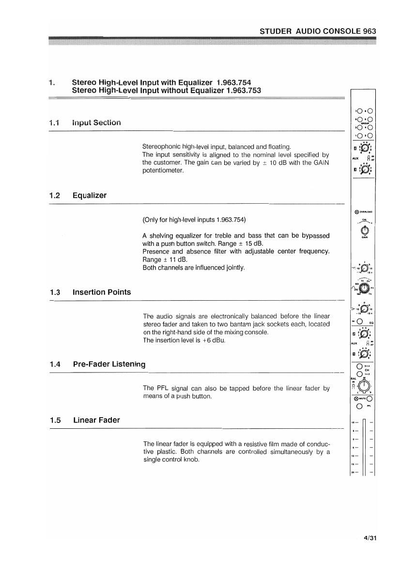
1. Stereo High-Level Input with Equalizer 1.963.754
Stereo High-Level Input without Equalizer 1.963.753
70 -O
. J ..o____.-_._u-_ -O-O
I.I lllpuloebllull 00
'0 'O
Stereophonic high-level input. balanced and floating. g géj;
The input sensitivity is aligned to the nominal level specified by M ' '.
the customer. The gain can be varied by z 10 dB with the GAIN ,.. "
potentiometer. 1 30}
1.2 Equalizer
Quin-um:
(Only for high-level inputs 1.963.754) .A.
m
A shelving equalizer for treble and bass that can be bypassed Y
with a push button switch. Range 1 15 dB.
Presence and absence filter with adjustable center frequency.
Range : 11 dB. .,
Both channels are influenced jointly.

1.3 Insertion Points
The audio signals are electronically balanced before the linear
stereo fader and taken to two bantam jack sockets each, located
on the righthand side of the mixing console.

The insertion level is +6 dBu.

1.4 Pre-Fader Listening
The PFL signal can also be tapped before the linear fader by
means of a push button.

1.5 Linear Fader .._ _
The linear fader is equipped with a resistive film made of conduc- :: :
tive plastic. Both channels are controlled simultaneously by a ..,_ _
single control knob. _ _

4/31

Page 2

STUDER AUDIO CONSOLE 963

1.6 Muting Switch
Push button switch with built-in pilot LED for click~tree, electronic muting of the
input channel.
The MUTE switch ca. be remote-contioiie" mat a connectoi locate" on the rear
panel of the console.
1.7 Auxiliary Outputs AUX 1... AUX 4
Four individually controllable auxiliary outputs can be fed before or after the linear
fader by means of push-pull switches on the AUX potentiometers.
1.8 Group and Master Selection
The master buses can be selected with 4 push buttons.
The group buses can be selected with 8 push buttons.
1 9 Balance Potentiometer
The balance potentiometer implemented as a combined push»pull control which in
the pulled state is effective for the channel direction assignment L-R. When the
knob is pushed in, the channels are balanced regardless of the rotary position,
1.10 Overload Indicator
The LED marked "Overload" turns on as soon as the maximum admissible level is
exceeded before or after the linear tader,
1.11 Signalling, Fader Start

4/32

The remote control relay in this module is activated as soon as the following con-
ditions are satisfied:

- Channel fader open
. Master fader open
- Mute button inactive

The normally open contact of the remote control relay is wired to a D-type
connector on the rear panel of the mixer.