Studer 189 Quadro Service Manual 3

This is the 80 pages manual for Studer 189 Quadro Service Manual 3.
Read or download the pdf for free. If you want to contribute, please mail your pdfs to info@audioservicemanuals.com.

Page: 1 / 80
left right
Studer 189 Quadro Service Manual 3

Extracted text from Studer 189 Quadro Service Manual 3 (Ocr-read)


Page 1

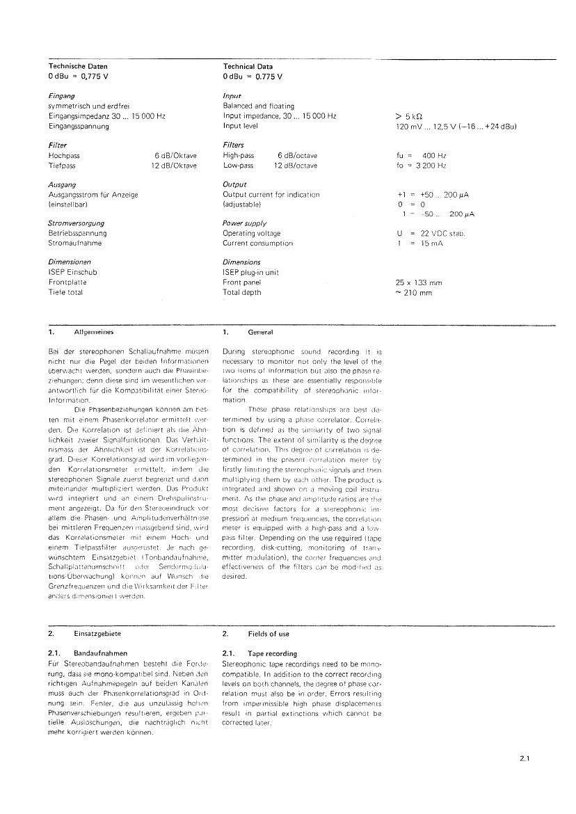
Technische Daten
0 dBu = 0.775 V

Eingang
symmetrisch und erdfrei
Eingangsimpedanz 3O 15 000 Hz

Technical Data
OdBu = 0.775V

Input
Balanced and floating
Input impedance, 30 15 000 Hz

>5l<fl

Eingangsspannung lnout level 120 mV .. 12,5 V (-16 +24 dBul
Filter Filters
Hochpass 6 dB/Oktave High-pass 6 dB/octave fu = 400 Hz
Tiefpass 12 dB/Oktave Low-pass 12 dB/octave to = 3 200 Hz
Ausgang Output
Ausgangsstrom fflr Anzeige Ontput current for indication +50 200 uA
(einstellbarl (adjustable) O

, 50 . 200 pA
Stramversargung Power supply
Betriebsspannung Operating voltage U = 22 VDC stat).
Stromautnahme Current consumption l = 15 mA
Dimensivnen Dimensions
ISEP Einschub lSEP plug-in unit
Frontplatte Front panel 25 x 133 mm
Tieie total Total depth ~ ZlO mm
1. Allgemeines 1. General
Bei der stereophonen Scliallaulnahme itiiissen During stereophonic sound recording it is

nicht ntir die Pegel der benden Informatmnen
Upemacht warden, soridern ducli die PltdStllllH
Ziehungen; denn diese sind iin WESellllltihen Vtil'
entwortlich tilt die Kempdtibilitat trinei Stereo
lntoimation.

Die Phasenpemehungen knnnizn am has-
ten mtt einern Phasenkorrelator efllllIIEElI in'iér'
den. Die Korrelaiion ist detiniert als the Alin
lichkeit zweier Sianiltunktionen Dtis Verhvilt-
nismass tler Ahnlichkeil ist der Korrelations-
grad. Ores-3r Korrelatinnsgiad wtrd llTl vorliegi'rt
den Karrelationsmetei EmchlL indem tlie
stereophonen Signzile zuerst begrenzt ttnrl dnnn
miteinander multiplizieit werderi Dds Prutliikt
word integriert und an einem Duelisptiliiistiii»
merit angezeigtt Da fur den Stereneindrtick tor
allern die Phasen urid Ainplitudenverhdltn
bei mittleren Frequenzeii inassgebentl sind, wird
das KOrrelationsmeter init eineiti Hoch Lind
einem Tietpassiilter aim Je nacli ge-
Wiinschtem Einszitzgebiet lTUfllMnddltlllBhlllt.
Schaltplattentimscnniti Seiiclurn'iuitila
tionstberwachungl konnm aul Wiinsch lie
Grenzlreatienzen und die tlk'SFllHktll der l' ilei
antlers rliniansionieit werden

Elllslel

Ltdm

necessary to monitor not only the level of the
iwu iteiris ol inlormation but also the phase re-
lationships as; these are essentially respt) with;
lot the compatibility of stereopltonic llllOl
mation

Those phase relationships 0H3 blSl te'
termined tiy using a phase izorrelator. Cumula-
tion is tleliried as the siinliaiity of two signal
functions The extent of similarity is the deqree
of CLllldlilllOll. This degiee 0t crirteiatinii l: i1:-
terminml in the pr: eni {O'RHIAUOH meter by
firstly limiting the str-zrenplmnir sigmls and tnrzn
multiplying them by each other The product is
integrated and shown (in ti moving cuil instril

meritt /\s W phase anti mnplttutle ratios are Ellr
most deciswe factors for a siereophonii; in»
pression at indium frequencies, the correlation
meter is equipped With a highepass and a law
pass filter. Depending on the use required (tape
recording, diskAcutting, monitoring of tram-
mitter modulation), the corner frequencies and
effectiveness of the filters can be moditietl as
desired.

2. Emsatzgebiete

2.1. Bandaufnahmen

Fiir Stereobandaufnahmen besreht die Portic-
rung, dais sie monorkonipdtibel sind. Neben dun
nchtigen Atiinahmepegeln aul beiden Kantilen
muss auch der Phasenkorrelatlonsgrad in Oid-
nting sein. Fenler. die aus unzultissig holmn
Phasenverschiebungen resultieren, ergeben tJl
tielle Atisipschungen. die nachtrttglich nicttt
mehr korrigiert warden kpnnen.

2 Fields of use

2.1t Tape recording

Stereophonic tape recordings need to be mono-
compatible. In addition to the correct recording
levels on path channels, the degree of phase cor-
relation must also be in order. Errors resultsng
from impermissible high phase displacements
result in partial extinctions which cannot be
corrected later.

2.1

Page 2

2.2. Schneiden Von Schallplatten
Normalerweise werden heuté Schallplatten ab
Band geschnitten. Das bedingt, dass die Auf~
nahme schon auf dem Band richtig, d.h. mono-
kompatibel, ist.

Stereoplatten werden bekanntlich in
Sctiragschriii (45°l45°) geschnitten Dabei entA
halt die Seitenschrift das Summen~ oder Mitten-
signal und die Tieienschrift das Differenz- oder
Seitensignal.

Zusatzlich zur MonOvKompatibilitat
muss nun noch darauf geachtet werden, dass die
Vertikalschrift keine allzu grossen Amplituden
aufweist, da sonst Deim Absoielen der Platte un<
zulzissige Verzerrungen auftreten konnen. Der
Korrelationsgrad bei tieien Frequenzen Lind
hoher Ansteuerung dart daher nicht zu klein
werden.

2.2. Cutting disks

Records are normally cut from tape recordings.
This means that the recording must be correct,
Le. mono-compatible, on the tape.

Stereoohonic disks are cut in oblique
recording (45°l45°). The lateral recording con-
tains the aggregate or mid-plane signal and the
vertical recording the diiferential or side signal.

In addition to the monovcompatibility,
care should be taken to ensure that the vertical
recording contains no excessive amplitudes.
otherwise impermissible distortions could arise
when the record is being plaved. Therefore. the
degree of correlation at low freouenmes and
high modulation should not be too small.

2.3. Sendermodulation

Die Modulation eines FM-Stereo-Senders erlolgt
mit dem Summensignal (Mine) Lind dem Dilr
ferenzsignal (Seite). lm Bereich 30 15 000 Hz
liegt das Summensignal, wéhrend dem die Sei-
teninformation als Zweiseitenband-Modulation
eines 38 kHz Hiltstragers abgestrahlt wtrd. Hohe
Differenzsignal-Frequenzen liegen am Rande des
Modulationsspektrums. Treten sie mit grossen
Amplituden auf, so konnen sie von mittelrntis
sigan Empfangarn nur mtirigelhafi demoduliert
warden. Die Verzerrungen steigen auch hier bei
zu kleiiiem Korrelationsgrad und hoher Aiissteu
erung an.

2.3., Transmitter modulation

The modulation of a FM stereo transmitter is by
means of the aggregate signal (centre) and the
differential signal (side). The aggregate signal
lies in the range 30 lSOOO Hz while the difr
ierential information is radiated in the form of
double side band modulation of a 38 kHz sub-
carrier High dillerential signal frequencies lie at
the edge of the modulation spectrum. It they
occur With high amplitudes, they can onlv be
imperfectly demodulated by the average re.»
ceiver. Distortions also increase in such a case if
the degree of correlation is too small and modtr
lation high.

3. Aniorderungen 2m ein Korrelationsglatt
meter

- Die ZLl messenden Signale sind schon DQI
kleiiieii Pegeln zu begrenzen uiirl in Ftliy
form wetter zu verarbeiten.

7 Die Signgile miissen in der Frequenz be-
wettet warden, sodass tiefe tint) hohe
Frequenzen gegeiitiher den rnittleteii we-
niger oerflnksichtigt werden.

- Diese Sewertung muss atifgenohen wer-
den, wenn die tiefen und hohen FieA
nuenzen hohe Pegel crreichen.

- Die Arizeige soll dLll einiache Art ge-
schehen, die eirio rasche und taiiizleutige
Anssage ergibi.

3. Requirements of a correlation meter

- The Signals to be measured must be Iirii
itetl a: low levels and treated further as
pulses

-- The signals must be ifeQUelllTV'V/Eigll[53d
so that low and high frequencies are
taken less into account, relative to me
dium frequencies

4 This Waighttng must be nullified ii the
low and high tieciuenmes reach high
levels.

-- The indication should be iIlTlpil) so as to
obtain a rapid and clear reading

4. Schaltungsbeschreibung

4.1. Blockschaltbild

Die Signals der ceideli Kariale durchlaufen
2 identische Ketten urid werderi einem Multipli-
kator zugeiuhrt. tier eine phasenabhangige Aus-
gangsspannung erzetigt, die auf einem Zeigerin-
strument angezeigt wird Das Instrument hat
den O-Punkt in tier Mitre (Korrelationsgrad 1 O)
und zeigt hit gleichphasige Signale +1, iiir gegen~
phasige --l.

4. Description of circuit

4.1. Block diagram

The Signals ol the two channels pass through
Zideiitical chains and are led to a multiplier
which produces a phase-dependent output vol t-
age shown on a display unit. The instrument has
the O-pomt in the middle (degree of corre-
lation=0l and shows +1 for in-phase signals
andAl for antiohase signals