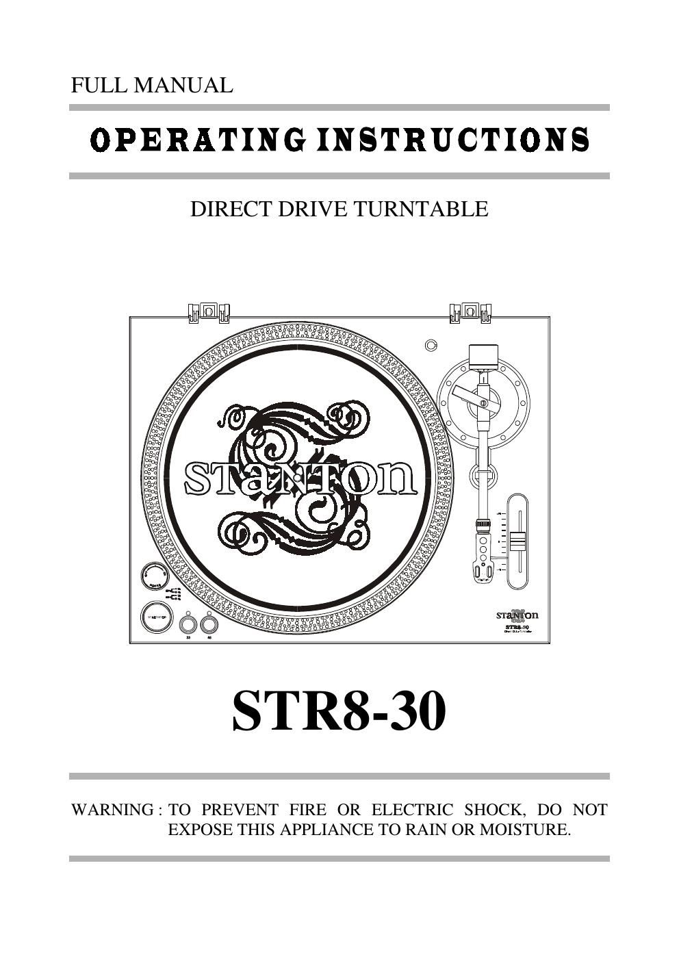
Stanton str 830 owners manual

This is the 4 pages manual for stanton str 830 owners manual.
Read or download the pdf for free. If you want to contribute, please mail your pdfs to info@audioservicemanuals.com.

Page: 1 / 4
left right
stanton str 830 owners manual

Extracted text from stanton str 830 owners manual (Ocr-read)


Page 1

NAME OF PARTS 2 3 4 5 6 7 8 9 10 14 1 13 11 12 1) Hi nge For Dust Cover 2) St robe Dot s 3) Slip Mat 4) C enter Spi ndl e 5) Power Switch 6) St art /Stop B utton 7) 33 B utton 8) 45 B utton 9) Headshell 10) Pi tch C ont rol Sl ider 11) Tonearm 12) Arm Rest 13) C ount erwei ght 14) Posi tion For Prepari ng C artridge B EFORE USE *C heck fol lowi ng part s i ncluded i n the package wi th the m ain unit: 1) Turnt able platter 2) Slip mat 3) Dust cover 4) 45-rpm adaptor 5) C ount erwei ght 6) Headshell 7) Operat ing instruct ions 8) RCA Cables wi th ground wi re *Not es: 1) Do not connect t he AC power plug before assem bly has been com pleted. 2) Before you turn on t he power, veri fy the vol tage set ting i s correct for y our count ry. 3) Read t his m anual careful ly before usi ng the uni t and be sure to store the m anual in a safe place for future reference.

Page 2

ASSEMBLY 1. Remove the main uni t wi th the packi ng from the box and t ake off t he packi ng. 2. Insert th e tu rntab le p latter o nto th e cen ter sp indle. 3. Set th e slip m at o n th e p latter. 4. Inst allation of cart ridge: When in stallin g a cartrid ge, refer to th e operatin g instru ctio ns of th at cartrid ge. Duri ng i nstallation, at tach t he st ylus prot ect or t o guard t he st ylus t ip from dam age. (1) Connect the lead wires to the cartrid ge term inals. The term inals of m ost cartridges are color coded. Connect each lead wire to the term inal of the sam e color. White (L+) .-¦....-¦-¦-¦-¦.... Left channel+ Blue (L-)....-¦-¦-¦............... Left channel- Red (R+) -¦-¦....-¦.......... Right channel+ Green (R-) .-¦-¦-¦..-¦......... Right channel- (2) Install th e cartrid ge to th e h ead shell an d tig hten it with screws p rovided with th e cartrid ge. 5. Insert th e h ead shell in to th e fro nt en d o f the tonearm , th en tu rn th e lo ck nut clo ckwise with the head shell firm ly h eld horizo ntally. 6. Slide count erwei ght ont o t onearm . Twist it lig htly an d it will screw o nto th e rear sh aft of the tonearm . 7. Adjust ment of hori zont al zero (0) bal ance and stylus pressure: (a) Remove t he st ylus prot ect or, do not touch the stylus t ip duri ng t he adjust ment. (d) Release the arm clam p and lift the tonearm from the arm rest to free it. (c) Rotate the counterweight until the tonearm is approxi mately bal anced hori zont ally (fl oat s freely). (d) Refasten the tonear m with the arm clam p. (e) Hol d the count erwei ght st ationary wi th one hand and rot ate onl y the st ylus-pressure ring to bri ng t he num ber "0" of t he ri ng into alig nment with th e cen ter lin e on the tonearm rear shaft. (f) Rotate the counterweight clockwise until the scal e shows t he val ue correspondi ng to the pressure of t he used st ylus. The average stylus pressure of t he cart ridge body is 1.5-2 g. If you use a non-St ant on cart ridge, pl ease fol low that m anufact urers i nstruct ions. 8. Install th e d ust co ver to th e m ain unit. PLACEMENT - Do not place the unit in a location where it will be exposed t o di rect sunl ight or near a heat ing appl iance. - Do not place the unit in a lo cation where there is high humidity o r a lo t o f dust. - Cartridge may pick up sl ight sound pressures or vibrat ions from the speakers com ing al ong t he floor or through the air resulting in feedback. Find a locat ion whi ch i s very stabl e and vi brat ion free. - The l egs have funct ions for adjust ing the hei ght of the u nit itself. Ad just th e leg s to stab ilize the main body hori zont ally. CONNECTIONS 1. Co nnect the p ower co rd to th e au xiliary p ower o utlet on the rear panel of your am plifier or receiver or to a househol d AC out let. 2. Connect the unit output term inals to the PHONO jack of your am plifier or receiver. Output term inals Am plifier(Receiver) L (W hite) >> L Ch annel R (Red ) >> R Ch annel GND (Spade) >> GND NOTE: Be sure t o connect the ground t erm inal firm ly to the am plifier or receiver. If t his connect ion i s not m ade or is loose, a power source "HUM" will resu lt.