Stanton m 201 owners manual

This is the 9 pages manual for stanton m 201 owners manual.
Read or download the pdf for free. If you want to contribute, please mail your pdfs to info@audioservicemanuals.com.

Page: 1 / 9
left right
stanton m 201 owners manual

Extracted text from stanton m 201 owners manual (Ocr-read)


Page 1

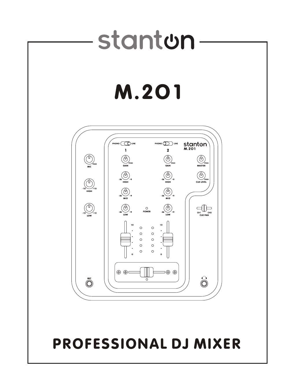
IMPORTANT SAFETY INSTRUCTIONS 1. Read these Instructions 2. Keep these Instructions 3. Heed all Warnings 4. Follow all Instructions 5. Do not use this apparatus near water 6. Clean only with dry cloth 7. Do not block any ventilation openings. Install in accordance with the manufacturers instructions. 8. Do not install near any heat sources such as radiators, hear registers, stoves, or other apparatus (including amplifiers) that produce heat. 9 . Do not defeat the safety purpose of the polarized or grounding-type plug. A polarized plug has two blades with one wider than the other. A grounding type plug has two blades and a third grounding prong. The wide blade or the third prong are provided for your safety. If the provided plug does not fit into your outlet, consult an electrician for replacement of the obsolete outlet. 10. Protect the power cord from being walked on or pinched particularly at plugs, convenience receptacles, and the point where they exit from the apparatus. 11. Only use attachments/accessories specified by the manufacturer. 12. Use only with the cart, stand, tripod, bracket, or table specified by the manufacturer, or sold with the apparatus. When a cart is used, use caution when moving the cart/apparatus combination to avoid injury from tip-over. 13. Unplug this apparatus during lightning storms or when unused for long periods of time. 14. Refer all servicing to qualified service personnel. Servicing is required when the apparatus has been damaged in any way, such as power-supply cord or plug is damaged, liquid has been spilled or objects have fallen into the apparatus, the apparatus has been exposed to rain or moisture, does not operate normally, or has been dropped. 15. This appliance shall not be exposed to dripping or splashing water and that no object filled with liquids such as vases shall be placed on apparatus. FEATURES

Page 2

MIXER CONTENTS 1. Input fader - Controls individual source levels (channels) in the mix. 2. Input toggle switch - Selects which source will be active based on what you have connected to the rear panel input section (phono/line). 3. Channel EQ - Adjusts the high, mid and low frequency levels of the input channels for good sound. 4. Channel Gain -“ Adjusts the pre-fader volume for cleaner sound. 5. Replaceable Crossfader - Achieves clean segues between the two input channels. "Hard left" selects Channel 1. "Hard right" se lects Channel 2. With the crossfader centered, both channels are live. Use the crossfader for fast and seamless segues (fades) from one channel to the other. Note: The crossfader is user replaceable in case of failure. Simply unscrew the two large screws which hold it in place, lift it out and disconnect its cable. Re-atta ch the new crossfader and screw the mounting plate back onto the unit - youre back in business! 6. Mic Input Gain -“ Adjusts microphone input level. 7. Mic Input -“ Insert your Microphone with ¼ plug here. 8. Headphone Input -“ Insert in the ¼ plug for your headphones here. 9. Channel Cue / Cue Pan - Used to preview channel audio to your headphones. Listen here before bringing up channel faders or moving the crossfader. 10. Headphone Level -“ Adjusts cue volume. 11. Master Level - Controls the overall output level. 12. Level Indicators -“ The dual LEDs indicators are us ed to indicate the master output level of channels Right and Left. 13. Mic EQ -“ The mic channel include a two- band EQ with a range of +10dB to -“10dB. 1 2 1 3 3 4 5 6 7 8 1 1 1 0 1 29